PRODUCT TECHNOLOGY

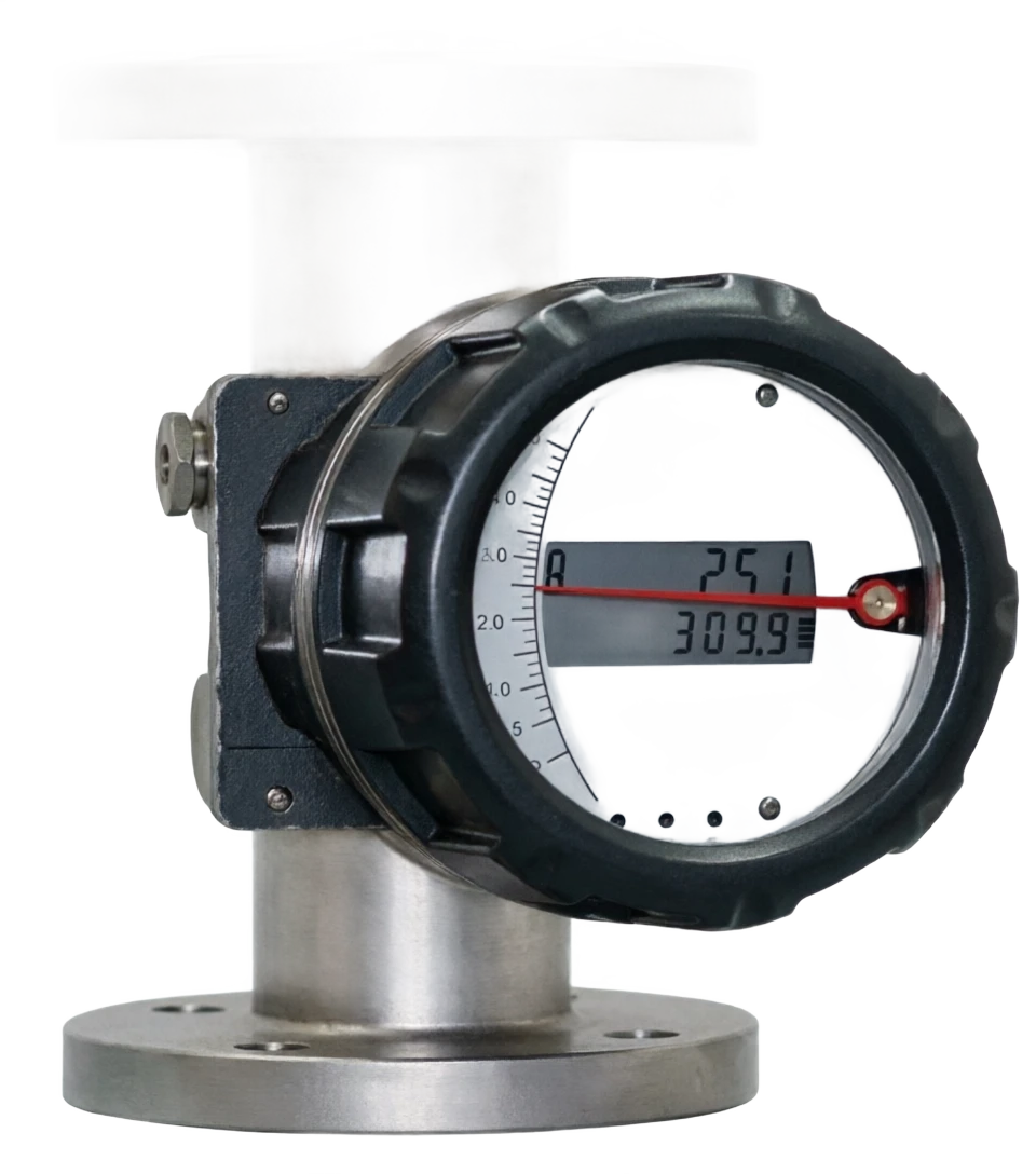
Metal pipe rotor flow meter

Operating principle

• The metallic tropometer.

When the flow increases, the float is lifted up, the circular overflow increases, and the float reaches a new position at the height of the pressure float h, the only balance (the float gravity = the fluid to the float + the fluid to the float). Alpha: Flow factor A(h): circular excess area V at the floating altimeter height h: float volume A: maximum amplitude of floats Old: fff float density Old: fluid density Q ⁇ h flow Q corresponds to float height H in short: h is read by tic or electron in defined media and floats. 0% scale indicator fluid entry 1 float flow method: fluid from bottom to upper float height h corresponding to flow Q level
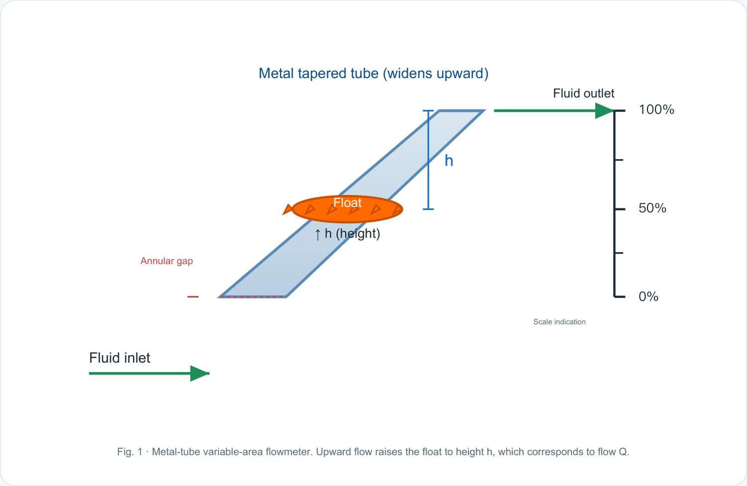
Metal cone tubes (downside and upward diameter gradually) Fluid exports 100% h float 50% h (high) loop gap 0% tics Flow entrance 1 Metal tube float flow method: fluids from down to upper float height h corresponds to flow Q
A schematic of the principles of work

Metal tube rotor flow metering support

Provide survey missions, media and installation conditions and obtain product configuration advice.

Contact us
· Technical Note

TECHNOLOGY & APPLICATION

Understand the principles, the exact selection.

The technical characteristics and selection elements of the metallic tube rotor flow meter are understood from measurement principles to field applications.

01

MEASUREMENT PRINCIPLE

Operating principle

Out.

When the flow increases, the float is lifted up, the circular overflow increases, and the float reaches a new position at the height of the pressure float h, the only balance (the float gravity = the fluid to the float + the fluid to the float).

Q flows, which are readable by magnetic coupling or mechanical transfer of float positions to external indicators.

Measurement formulaClick to see the big picture
Q = α · A(h) · √(2gV(ρ−ρ) / Aρ)
f f f
Alpha: Flow factor A(h): circular overflow area V at H of float: float volume A: maximum amplitude of float: old:
f f f
Float density Old: fluid density
Measurement formulaClick to see the big picture
Q ⁇ h flow Q corresponds to the float height h In short: under the defined medium and float, read h or Q by tic or electronic means.

fff

Technical IconClick to see the big picture
Metal cone tubes (downside and upward diameter gradually) Fluid exports 100% h float 50% h (high) loop gap 0% tics Flow entrance 1 Metal tube float flow method: fluids from down to upper float height h corresponds to flow Q

Key premises

Vertical installation must (bottom-up) ensure that the float is only balanced by gravity, buoyancy and fluid kinetic pressure; flow must be measured by actual flow of media and different media need to be re-ticulated because of density and viscous differences.

  1. 01

    The metallic pipe float is a "floating" flow count.

    A floating object, a floating formation. The fluids enter from below, flow between the float and the tube wall.

  2. 02

    The cone metal tube, which is gradually being expanded from the bottom up, and the inner ring gap of the tube, flowed from above.

02

PRODUCT STRUCTURE

Structure

The metal-tube variable-area flowmeter comprises a tapered metal tube with flanges, a float, a magnetically coupled indicator, and a signal converter or remote transmitter. Options include a local pointer display and 4–20 mA / HART output.
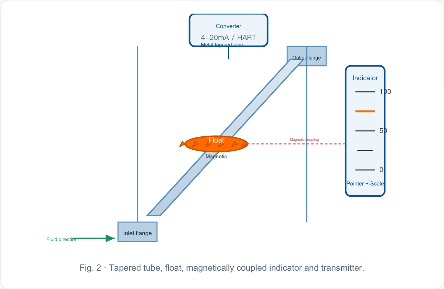
Transverter 4-20mA / HART Metal Cone Plumber Indicator 100 Float Magnetic Concord

Tape

Pointer + scale entry French Fluid Direction 2 Metal pipe float flow meter profile

Conesian tube + float + magnetic coupling indicator + converter

Form and float

Metal cone tube

304 / 316 stainless steel, high pressure, resistant to high temperature corrosion

Float.

Magnetic stainless steel / titanium / Hapsy alloy, etc., selected in media

Up and down Frank / Thread

Connect to process pipe

Inline (optional)

PTFE / PFA / Rubber for strong corrosive media

Instructions and signal units

Magnetic coupling indicator

Magnetic float inside the tube with the external magnetoscope, pointer + scale

Electronic remote converter

Magnetic Sensors ⁇ 4-20mA / HART / RS485

In situ LCD Display

In a moment + cumulative flow

Call the alarm switch (optional)

Upper-Land Call / Pulse Output

Technical IconClick to see the big picture
Converter
4-20mA / HART
Metal cone tube
Exporting Frank.
Indicators
100
50
Float, magnetic coupling.
Tape
0
Pointer + Scale
- Frank.
Fluid direction
Figure 2 Metal pipe float flow meter structure profile: cone tube + float + magnetic coupling indicator + converter
03

TECHNICAL GUIDE

Advantages and disadvantages

Advantages

Simple, solid.

Structure

High pressure resistance, high temperature resistance.

Not under medium pressure.

Measurement results

Impact (distinguishing from differential pressure)

Small pressure (compared to holeboard, vortex)

Scale Intuitive

The structure is transparent,

# Live readable #

Particularly sensitive to small flows, low flow speed, medium wide

Liquids, gases, steam

In situ.

Remote Transfer Out

I'm sure.

, or maybe.

(4-20mA/HART)

Disadvantages / Limitations

It must be installed vertically (downward-up) and the direction of the installation is restricted

Limited range, usual 1

10

Density, viscosity

Measuring precision mediums

Impact (different media to be remarked)

Sticky/repeated

Floating is in long run

Problem

The dirty agent is sensitive.

The particles are bound to the large-calibre float (DN150 or more) and are thick and expensive (early product) glass tubes that are fragile; metal pipes are improved but cost increases

04

APPLICATIONS

Application area

Chemical process

In situ instruction and control of acid alkaline, corrosive media

Food and drink

Health-level applications, CO₂, N₂, etc.

Steam and gas

Vapour, compressed air, protection of air, etc.

Laboratory/testing

Small flow precise indications, process development.

Pharmaceutical industry

Pure liquids, injection water, raw material drug measurement

Water treatment

Small flow measures for pure, circular, plus-drug systems

Petroleum chemicals

Auxiliary measures and field display of process pipes

Environmental protection and wastewater

Adding systems, reagent flow monitoring

05

TECHNICAL SPECIFICATIONS

Technical Parameter Table

  1. 01

    The reference table for flow ranges (caliber flow) is shown in the table below. Liquids by typical condition (adhesive close to water, density 1.0 g/ cm³); Gases measured at constant pressure constant m³/h; Actual scope

Changes with the density and viscosity of the medium.

  1. 01

    Liquid flow (m³/h, reference water) DN40DN125/DN150

  2. 02

    25

  3. 03

    0/6.040/60

  4. 04

    Gas flow (specify m³/h, reference air) DN40DN125/DN150

  5. 05

    0/1060/100

Technical parameter table · Parameter item / IndicatorCross-reference
Parameter ItemIndicatorsParameter ItemIndicators
Measured mediumLiquids, gases, steamPower supply24V DC
Nominal pressure1.6 / 2.5 / 4.0 / 6.4 / 10.0 MPaIngress protectionIP65 / IP67
Turndown ratio1:10 (Part 1:5)Inline (optional)PTFE / PFA / Rubber
MountingVertical installation (down-to-up fluid)Ambient temperature20 ℃ ~ 60 ℃
Technical parameter table . cal. (mm) / Minimum flowCross-reference
Nominal size (mm)Minimum flowTop flowNominal size (mm)Minimum flowTop flow
DN200.040.4DN651.010
DN320.161.6DN1002.525
Technical parameter table . cal. (mm) / Minimum flowCross-reference
Nominal size (mm)Minimum flowTop flowNominal size (mm)Minimum flowTop flow
DN200.070.7DN651.616
DN320.252.5DN1004.040
06

SELECTION GUIDE

Selection Guide

  1. 01

    Five-step selection.

  2. 02

    Speculative liquid / Gas / Steam

  3. 03

    Normal flow of fixed traffic + minimum/maximum

  4. 04

    Calvity selected and float by flow + medium density

  5. 05

    Select the material and the liner by medium corrosiveness + temperature

  6. 06

    Directives and output in situ / Remote 4-20mA

  7. 07

    Floating material selection

Floats are the only motion that directly contacts the medium, and the material must be resistant to the medium ' s corrosion and temperature.

Aluminium / special ceramics, light field special applications by mass

  1. 01

    Medium - Float Shape Selection

  2. 02

    Media-flow selection type 30% ~ 80% normal flow should be controlled by the range

, the position of the microfloat is unstable, the large reading enters the nonlinear zone.

  1. 01

    Instructions and remote alarm pointer + alarm switch + 4-20mA upper and lower limit alarm, lot control

When the density changes significantly) the scale needs to be re-corrected.

  1. 01

    Selecting Hints

    Metal pipe float flow requirements

  2. 02

    Mark with actual medium flow (or with converted equivalent); switch to medium (e.g.)

Selective guidance · Floating material / Applies mediumCross-reference
Float materialSuitable mediaTemperature rangeCharacteristics
Titanium TiSeawater, chlorinated, oxidizing media80 ~ 200 ℃Congestion resistant to chlorine ions
PTFE / PFA OverwriteStrong acid, strong alkalin, super-purified medium40 ~ 180 ℃Almost all chemicals are tolerated
Selective guide . Floating shape / flow characteristicsCross-reference
Floating shapeFlow characteristicsSuitable mediaCharacteristics
TrayApproximate LinearLiquid, small flowSmall caliber is common.
Cones / AlienCustomSpecial mediaHigh viscosity, dirty pollution medium
Selective guide . Media type / Typical flow speedCross-reference
Media TypeTypical flow speedDensity rangeSticky RequirementsAnnotations
Heavy liquids, crude oil0.3 ~ 2 m/s0.8 ~ 1.5 g/cm³≤ 100 COMP (selected floats)Need to fix by viscosity
Steam3 ~ 20 m/s——High temperature, density. Compensation.
Selecting guide . Type / DisplayCross-reference
TypeDisplaySignal outputApply scene
Teleport (simulation)Pointer + 4-20mA4-20mATraditional DCS / PLC access
bus typeLCD Number DisplayRS485 / ModbusMultiple network monitoring