PRODUCT TECHNOLOGY

Smart differential transmitter

Operating principle

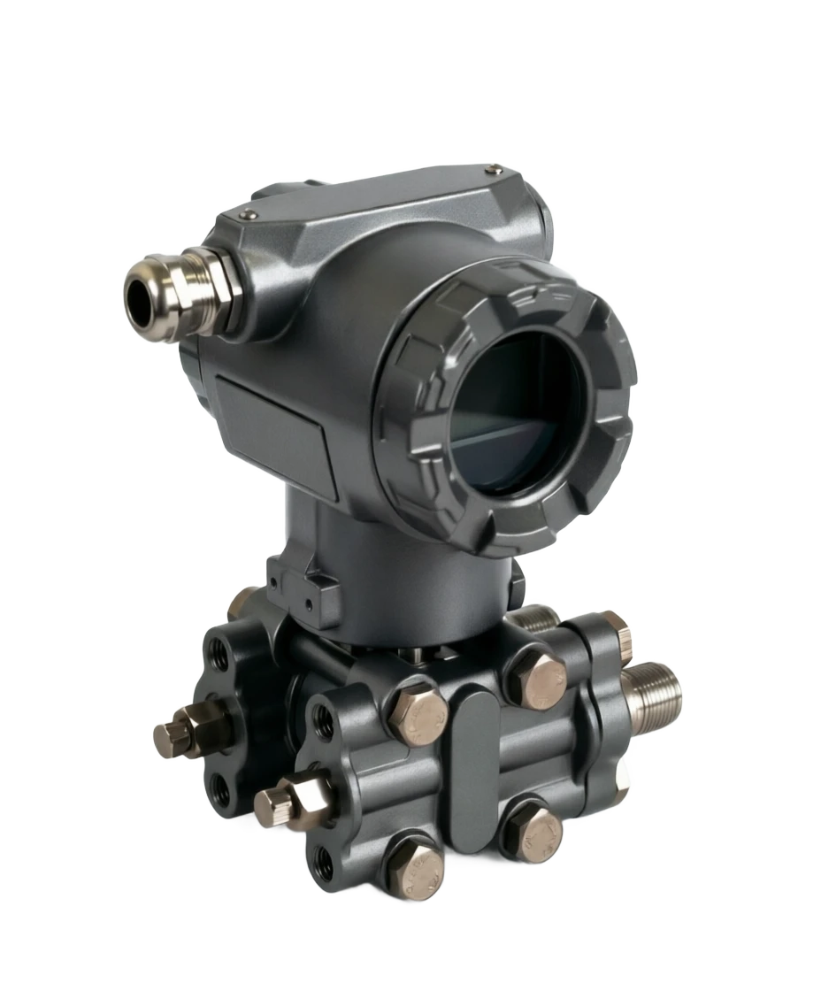
Smart differential transmitter.

High and low pressure side process pressure is transmitted to the central measurement film by separate amplification + filling fluids, which causes the measure film to undergo a micro-diverse shift (maximum 0.1 mm) to the differential pressure, and is converted from sensor to telecommunications: Metal Capacitive (3051CD): the shift changes the differential motor of the measured film to the fixed polar plate on both sides, the power margin is amplified, the A/D conversion is processed by microprocessors for export; Single-crystal silicosis (EJA110E): two H-shaped silvimation beams are made from the centre and the edge of the single-crystal silic chip, which is pressured by the pressure (reduced frequency), the edge beam is pulled (upped frequency), and the difference between the two-frequency is sent directly to the CPU processing - natural digital signals, free of A/D conversion error; Dynamic compensation: digital sensors such as DPharp

  1. 01

    Flow measurement . Irrepressible flow method: Fluid-saving devices (poreboard/V-cone/ nozzle/ aoxen) generate differential pressure . q ⁇ ⁇ P ⁇ K, formulae (delaying of the carrier's inner or DCS opening)

  2. 02

    Liquefied measure · LCD = density x LSD height = ng, often with a migration offset for the hydraulic column; closed tank with a bi-franc transmission

  3. 03

    • Discharge pressure of fixed height liquid column changes with density

  4. 04

    Interfacing/stratification Measurement . Distortion changes caused by changes in the two media interfaces .. two phase densitys, often combined with two French

Smart differential transmitter selection support

Provide survey missions, media and installation conditions and obtain product configuration advice.

Contact us
Smart differential transmitter . Technical note

TECHNOLOGY & APPLICATION

Understand the principles, the exact selection.

From measurement principles to field applications, the technical characteristics and selection features of the smart-disk deliveryer are understood.

01

MEASUREMENT PRINCIPLE

Measurement principle

1.1 Distress measurement links

High and low pressure side process pressure is transmitted to central measurement film by separate separators plus filling fluids, which produce a difference between the two sides.

Micro-division (maximum 0.1 mm) converted from sensor elements to telecommunications: Metal Capacitive (3051CD): Bit-to-place change of the differential electric capacity between the measured film and the fixed polar plate on both sides, with the capacity differential being amplified and A/D conversion processed by microprocessors for output;

Single-crystal silvionic (EJA110E)

(a) The single-crystal silicon chip centre and the edges produce two H-shaped coordination beams, which are pressured by the pressure (reduced frequency), the edge beam is pulled (upped frequency), and the difference between the two frequencies is sent directly to CPU processing - natural digital signals, free of error in A/D conversion;

And static pressure transforms the beams in the same direction, and the same frequency, and the deviations are automatically eliminated, and the static pressure effect is close to zero.

1.2 Four applications with a pressure difference

1.3 Smart capacity (discretionary)

Dynamic compensation

Digital sensors such as DPharp measure the differential/static/temperature three variables simultaneously, eliminating temperature and static effects in real time;

Combination of the sensor

(a) A transmitter that simultaneously produces a difference and static pressure, saves the independent static transmitter (savings of approximately 20% CAPEX);

10-part signal curve expression

(b) The output linear correction of non-linear applications such as tanks, flow;

Open and small signal cut

(b) The flow application of internal opener functionality and low flow cut (avoiding ⁇ P to magnify noise near point zero);

The baroque block diagnosis.

Early warning of blockages by statistical characteristics of differential signals.

The principle of measurement . Application / mechanismCross-reference
ApplyMechanismKey formulae/conditions
Flow measurementIMR: Fluid-switching devices (poreboard/V cone/ nozzle/oxoba) produce differential pressureq ⁇ P ⁇ K, coding formula (deletor inner or DCS opening)
Liquefied Level MeasurementSquire pressure = density x liquid height= Zip, often required to carry the displacement off the hydraulic column; closed cans required for transmission to two French languages
Density measurementThe pressure of the fixed height column varies with densityOld = ⁇ P/(g.h), points high-pressure
Interface/Step-Stage MeasurementThe difference in pressure caused by the change in the interface between the two mediaYou know, two-symmetrical, two-brand.
02

PRODUCT STRUCTURE

Structure

2.1 General structure

Process side (sensor membrane box)+ Electrical side (electronic shell) two-part, Coplanar plane co-co- interface (3051 feature): The high-pressure bar is located on the same plane and can be fitted directly with a trivalve/quint or integrated throttle-saving device, reducing 70% of the pressure-exposure point.

2.2 Sensor membrane cartridges

Isolation diaphragm

316L (coding), Haq Alloy C-276, Alloy 400 (Monnell), tantalum, plating alloy 400/ plating 316L (hydrogen)

Fill fluid

Silicon oil (standard), inert oil (no-oil field), high-temperature oil;

One-way over-pressure protection

(b) The membrane and membrane box body is supported by a ripple process, the ultra-pressure-time membrane accelerator, and the silicon oil pressure is no longer transmitted - EJA overpressure 220bar, 3051 overpressure maximum 414bar, without damage and no re-recommendation after normality;

Capsule.

The range of the differential pressure is divided into the L/M/H/V membrane slotting (micro-pressure to high pressure differential), and the same shell membrane box is the change range.

2.3 Electrical component

Output 4~20mA + HART 5/7; optional FF field bus, PROFIBUS PA, BRAIN, WirelessHART, 1-5V DC low-capacity HART;

Internal display table

(a) Independent circuits, showing measurements, alarm codes, bar charts, programmable settings;

Local Parameter Settings (LPS) button

The use of hand-managers to change the scale on the ground is not possible;

Fireproof.

Ben An/Dubian-Insistence Certification; SIL2/SIL3 (TUV & Exida).

2.4 Installation packages

2.5 Model Spectrometry

Thrust (traditional)

Note: Transmitters + barbed wire + trivalves, applicable to general conditions

Integrated trivalves direct

Note: 305 Series valves directly fit the Coplanar interface, save the pressurization tube

Telefilm Seal (1199 classes)

Note: Cough tube + French film seal, high sticky/crystal/corrosion/vacuity

Integrated throttle-saving devices

Note: Plant pre-filled perforation/Arnba + Transmitter fully marked, ready to be installed

Multivariate (MV)

Note: Difference pressure + static pressure + process temperature three parameters for gas/vapour flow temperature reimbursement

Vendor/system

Main pressure type, special type

Emerson.

3051 CD (Standard Wreshold) 3051S (High Performance), 3095 MultiVariance, 3051 User Rembrandable Box

River

EJA110E / EJX110A EJA120E Microdiscretion, EJA130E high static pressure (4,500psi), EJA210/220 bi-franc fluid level, EJA310 insulation

National production

Kawaru PDS, Control, Mac, etc. Precision 0.075 ~ 0.1%, value route

03

TECHNICAL GUIDE

Advantages and disadvantages

3.1 Advantages (10 items)

Flow/liquid level/density/interface I table common

(a) Worm pressure is the most common intermediate variable in the process industry, with a single component being the system;

Precision

EJA110E ±0.055% (optional ±0.04%), 3051CD ±0.075% (high ±0.04%);

Long-term stability is excellent.

EJA ±0.1% URL/ 10 Year, 3051 0.125%/ 5 Year, free of frequent adjustments;

The pressure is extremely low.

Single-crystal silvionic bisole structure static pressure is removed; the capacitation is digitally modified by static sensors;

One-way over-pressure protection is excellent.

220 ~ 414 bar undamaged pressure without having to re-recommend, and without damage to the valves;

Scale ratio 100

1 + is highly mobile: is moving 500%, negative is moving 600%, and is widely used for liquid-level transport;

Come on, come on.

90~150 ms, refresh rate > 20 sec/s to meet flow control dynamics;

Strong diagnostic and safety capabilities

Blocked tube diagnosis, back-to-back self-examination, SIL2/3 certification, available in SIS;

High setup

Integrated valves/scaling devices/dispersive film, plant whole marking, half-hours of installation;

Protocol All Over

HART/FF/PA/BRAIN/Wirewire, integrated into mainstream DCS and equipment management systems.

3.2 Limitations (10 items)

The essence of the measure is the pressure, not the flow itself.

Flow accuracy also depends on the throttle-saving devices, density, temperature compensation, and system error may be much greater than the carrier accuracy;

The barbed wire is weak.

(b) Creature, gas, congestion, leaks to the head of the failure of the differential pressure system (particularly vapour/dust-containing media);

Large precision downscale of scale

More than 10 : 1 Post-precision from 0.075% Down to 0.1 ~ 0.2% , the extent of the bandwidth is subject to accounting;

The pressure limit is limited.

(b) Low limit of static pressure under the differential pressure range, with a large percentage of static pressure error, and high static pressure differential, which is selected for the high static pressure type;

Open output zero is unstable.

The misset of the small flow signal tectonics can cause small flow or zero-point drift;

High prices

Import type is dozens of times the normal margin table, and the price of the valve set/extension is doubled;

24VDC required backtracking and ancillary works

(b) The combined costs of safety fences, cables and valves;

Long-spread catheter with delay and temperature error

Changes in temperature and concentration of charge in the catheters measured in bi-fascular fluids need to be amended;

Risk of hydrogen infiltration and film erosion

Gold membranes shall be coated in hydrogen gas, and the Zhuha/Tya will be severely corroded and will be erroneously disposed of;

Vibration and installation posture effects

The pressurized installation is sensitive to the pressure point height difference, the carrier position and does not regulate the introduction of additional errors.

04

APPLICATIONS

Application area

4.1 Typical application scenarios

4.2 Selective positioning judgement

Measuring flow

(b) The first flow control programme (poreboard/V-cone/Avera) and then the maximum margin for the selection of the carrier slot;

Liquidity Level

Open-pits are mono-French/input, closed cans are spread over two-franic and safe liquids such as car bags are highly reliable + redundant;

Micropressure differential (clean room, furnace chamber)

Micro differential pressure type (minimum 0-25 Pa up);

Media crystallization/high sticky/ strong corrosive

It's always a long-range film seal, not a barbed wire.

Petroleum

Flows: Pyroscope/V cone for vapour, raw oil flow Liquefied: distillation tower plume, storage tank (bi-Franc) Liquefied Other: reactor bed pressure differential, catalyst density

Electricity

Flows: main steam flow, water flow liquid level: carton level (key safe return path, constant three times redundant) Other: furnace wind pressure, carving vacuum

Natural gas

Flows: Trade measurement of the vents of the distribution station (multivariant thermovoltage supplement) Liquefied: Separators interfaces Other: Network pressure differential monitoring

Water treatment

Flows: Exposure flow (Axaba) Liquefied level: filter fluid level other: filter pressure differential (resilver-scrution judgement)

Pharmaceutical food

Flows: sanitary flow Level: sterile tank fluids (carphythmic film) Other: clean room pressure differentials (micropressure slots)

Metallurgy

Flows: high-bore gas flow Liquefied: Label fluids Other: pressure differentials on top of the furnace

Pulp, paper.

Flows: - Liquid level: Vapour tower level (high stick/crystal transmission) Other: Bulk pressure differential

05

TECHNICAL SPECIFICATIONS

Technical Parameter Table

  1. 01

    1 General technical parameters (EJA110E / 3051CD benchmark)

5.3 Membrane boxes/quantitative slotting table (conceptal)

Technical parameter table · Item / ParametersCross-reference
ItemParameters
Measurement typeDifference pressure (measurable flow/liquet/density/interface)
Pressure range0~25Pa (micropressure type) to 0~13.8/14 MPa (2000psi); EJA General - 100~24000kPa
Reference Precision± 0.055% (EJA-E)/ ± 0.075% (3051); high ± 0.04%
Turndown ratio100:1
Long-term stability±0.1% URL/ 10 year (EJA); 0.125% / 5 year (3051)
Maximum static pressure2300 psi/16 MPa (general); EJX and 3051S to 3600psi; EJA130E 4500 psi/31MPa
Overcrowding protectionSingle-direction overpressure 220bar (EJA) ~ 414bar (3051) undamaged, non-rehabilitation
Response time90ms(EJA)/ 100~150ms(3051)
Output signal4~20mA DC + HART 5/7; FF/ PROFIBUS PA / Brain / WirelessHART / 1~5V low-capacity
Electricity12~36VDC (this is a security fence)
Ambient temperature40~85℃
Process medium temperature40 ~ 120°C (higher than the high temperature silicate oil)
Wetted materials316L / Ha, C-276/Alloy 400/ tantalum / alloy plating 400/ Plating 316L
Migration capacity500% positive, 600% negative (minimum course of change)
Explosive/securityBenan i IIC T6 / Insulation d IIC T6; SIL2/SIL3 (TUV & Exida)
Ingress protectionIP66/IP67/IP68
Show TableIndependent circuit interior display, programmable
Execute/AcquisitionGB/T 17614, IEC 61508; JJG 882 verified
ParametersTrans-Hand River EJA110EEmerson 3051 CD
Sensory technologyDPharpMetal capacitor
Reference Precision±0.055% (optional ±0.04%)± 0.075% (high ± 0.04%)
Stability± 0.1%/10 years±0.125% / 5 years
Response time90ms100~150ms
Overpressure220barMaximum 414 bar
The static pressure is eliminated.Structural self-eliminationDigital static pressure compensation
Diagnostic characteristicsFrequency signal self-checked continuouslyBlocked diagnosis/return route diagnosis mature
EcologyThe Japanese system is more equipped with more.The largest global load, wide network of services
Technical parameter table . Membrane box / differential rangeCross-reference
Menm BoxPressure rangeMaximum static pressureTypical uses
L (microvolt)0~0.1~6kPaLowThe chamber pressure, the clean room.
M (low differential pressure)0~6~40kPa14~16MPaRegular flow, liquid level
H (middle pressure)0~40~250kPa16~31MPaMedium-high pressure differential flow
V (high differential pressure)0~0.25~14MPa31MPa+High pressure differential, high static pipe lines
06

SELECTION GUIDE

Select Table

6.1 Required parameters for ordering

  1. 01

    Use

    Flow / LID / Density / Interface / Pure pressure;

  2. 02

    Pressure range

    Normal/maximum/minimum value (flow is given in the flow book);

  3. 03

    (b) Silent pressure (work pressure) - the first check item of the differential pressure selection;

  4. 04

    Media names, corrosiveness, viscosity, crystallization/specific content;

  5. 05

    Temperature of the medium, ambient temperature;

  6. 06

    Mounting

    (a) Thrust / integrated valves / tele-film (cruise tube length, French grade and material);

  7. 07

    Precision and SIL requirements (whether to enter SIS or not);

  8. 08

    Output protocol (HART/FF/PA/Low-ow);

  9. 09

    (a) Relaying liquids and filling fluids (prohibited oils);

  10. 10

    Show the surface, blast-proof level, and attachments (triple/quint/cool tank/irrigator).

6.2 Measuring mission decision tables

6.3 The rules for the selection of the scale and accuracy

The range of the differential is at maximum pressure. 1.2 ~ 1.5 Multiplier, take into account normal operations points (%) 25% ~75% URL);

The scale is as much as possible. ≤10

1 Precision; wide-flow ranges consider double tables and linked or account for downscaling accuracy;

Liquidity negative transport

⁇ Old g.h (pricing tube fluid) to check not to exceed the negative migration 600% limit;

Micro differential pressure high pressure condition

Checking static pressure error indicators (micropressure slotting static effect of up to ± 10%, with a high-pressure type selected).

6.4 Example of Model Preparation (EJA110E)

Technical IconClick to see the big picture
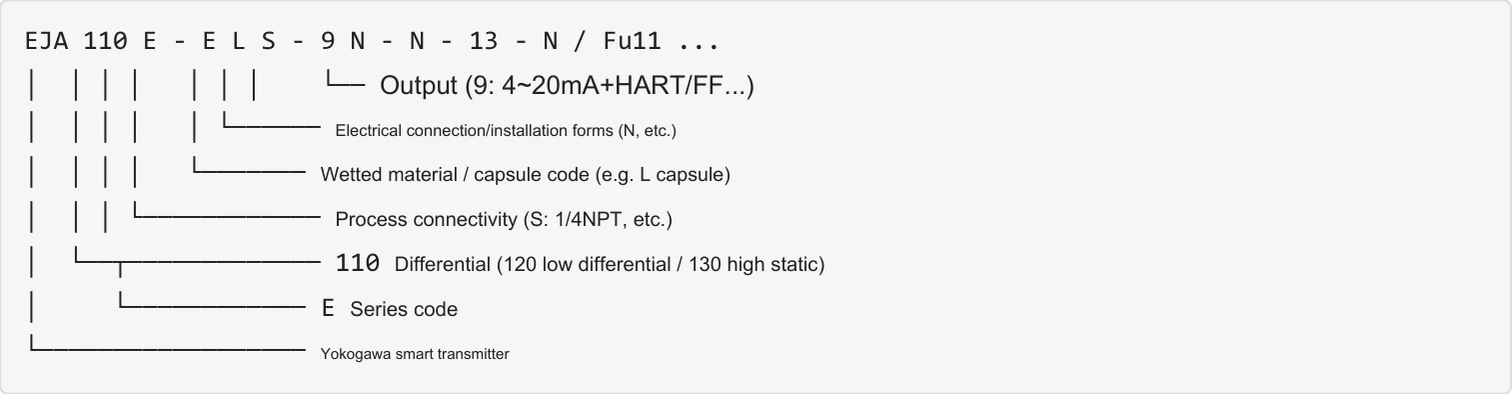
EJA 110 E - E L S - 9 N - N - 13 - N / Fu11 ...
│ │ │ │ │ │ │ └── Output (9: 4–20 mA + HART/FF…)
│ │ │ │ │ └────── Electrical connection / mounting (N, etc.)
│ │ │ │ └─────── Wetted material / capsule code (e.g. L capsule)
│ │ │ └──────────── Process connection (S: 1/4 NPT, etc.)
│ └──┬───────────── 110 differential (120 low differential / 130 high static)
│ └──────────── E series code
└────────────────── Yokogawa smart transmitter

The Quasi Smart Transmitters (3051 CD) model is presented in sister's "Intellectual Pressure Transmitters Technology Summary."

6.5 Selective elements and use maintenance

  1. 01

    Still pressure ahead of the scale check

    The static pressure limit is the first source of the differential pressure type;

  2. 02

    Three valves operating discipline.

    (b) The application of first-on-the-off balancing valves, and then the off-off-the-off-the-low-pressure valves - preventing one-way shocks (although 220bars are protected by over-pressure, they are executed in accordance with the protocol);

  3. 03

    The pressure tube design

    Liquid pressure measurement is for exhaust (render less than pressure point), gas pressure measurement is for discharge (render higher than pressure point), vapour must be fitted with condensed tanks and two cans tall;

  4. 04

    Zero-point migration verification

    (b) Validation of zero points before the liquid level is put into operation, with minor adjustments to zero points in the running periodic HART;

  5. 05

    Small signal cision settings

    The flow opening output is cut by 5%-10%, avoiding zero noise magnification;

  6. 06

    I'm going to send a message to the two French.

    Two catheters, etc., are prepared to avoid single-side sunburning and temperature correction at high accuracy;

  7. 07

    Oil/hydrogen ban

    (b) Write about inert oil filling and gold-plugged film;

  8. 08

    Mine-protected and grounded

    Signal cable shielding single points, with a flood protection in mined areas;

  9. 09

    Periodically rated JJG 882, with smart models that can be remotely validated by HART to reduce the dismantling workload;

  10. 10

    Safety fluid redundancy

    The SIS return route uses IEC 61511 for redundancy (2 oo3) and periodic performance tests.

Select Table . Task / Recommended ConfigurationCross-reference
TasksRecommended Configuration
Vapour flow (poreboard)Fragmentation + trivalves + condensed tank + temperature compensation (or multivariate)
Clean liquid/gas flowFragmentation + integration valves to be installed
Closed tank liquid slot (clean media)The differential type + double-thrust + negative migration
High sticky/crystal-can fluid levelBi-French long-distance + hair tube (select the length of the catheter and charge)
Safety fluids, including carbags.High stability (3051S/EJX) + Three to two redundancy + SIL3
Cleaning room/bore micropressure differentialMicrodiscretion membrane box (L-file)
Gas trade measurementMultivariant (DP+P+T) or advanced flow computer package
07

TECHNICAL GUIDE

Horizontal comparison table

7.1 Smart differential transmitters vs. Other flow/lique level measurement programmes

7.2 Selective mouthpieces

Flow fluids are subject to differential pressure and flow-saving books are first slotted; The static pressure check is the first, with a scale of : to ; (a) High, e.g., steam condensers, with a clear negative displacement of liquid levels; Crystals are superglued to a long-distance, micro-discretionally selected L film box; Three valves are in sequence, open to five to ten; The bag water level SIL Three, three to secure two.

This summary technical parameters are based on official samples of GB/T 17614, JJG 882 and Rothmont 3051CD, EJA110E/EJX, which are based on the latest samples from the manufacturer.

Horizontal Comparison Table · Contrast / Smart Flowers (System)Cross-reference
ComparativeSmart differential transmitter (scaling)Corcelium Quality FlowometerElectromagnetic flowmetersRadar Liquefied
Measurable TasksFlow/liquid level/density/interface/discretion pressureQuality flow (+density)Electro-liquid volume flowLiquidity/Interface
Precision (system)Transvestitions 0.075%, systems 1% ~ 2%0.05~0.2% (system level)0.5%1~3mm
Turndown ratio10:1 ~30:1 (flow system)20:1~500:110:1~100:1—
PressureYes (scalable)Small ZoomNoneNone
Media LimitWide (extensible)Gases can be all.Must conduct electricityLiteral constant limit
PriceLow ~ Medium (Medium-High-Six)HighestMediumMedium ~ High
Typical advantagesTable multitask, SIS authentication, eco-maturityTrade measurement precisionNo pressure loss maintenanceNot exposed, not affected by density