PRODUCT TECHNOLOGY

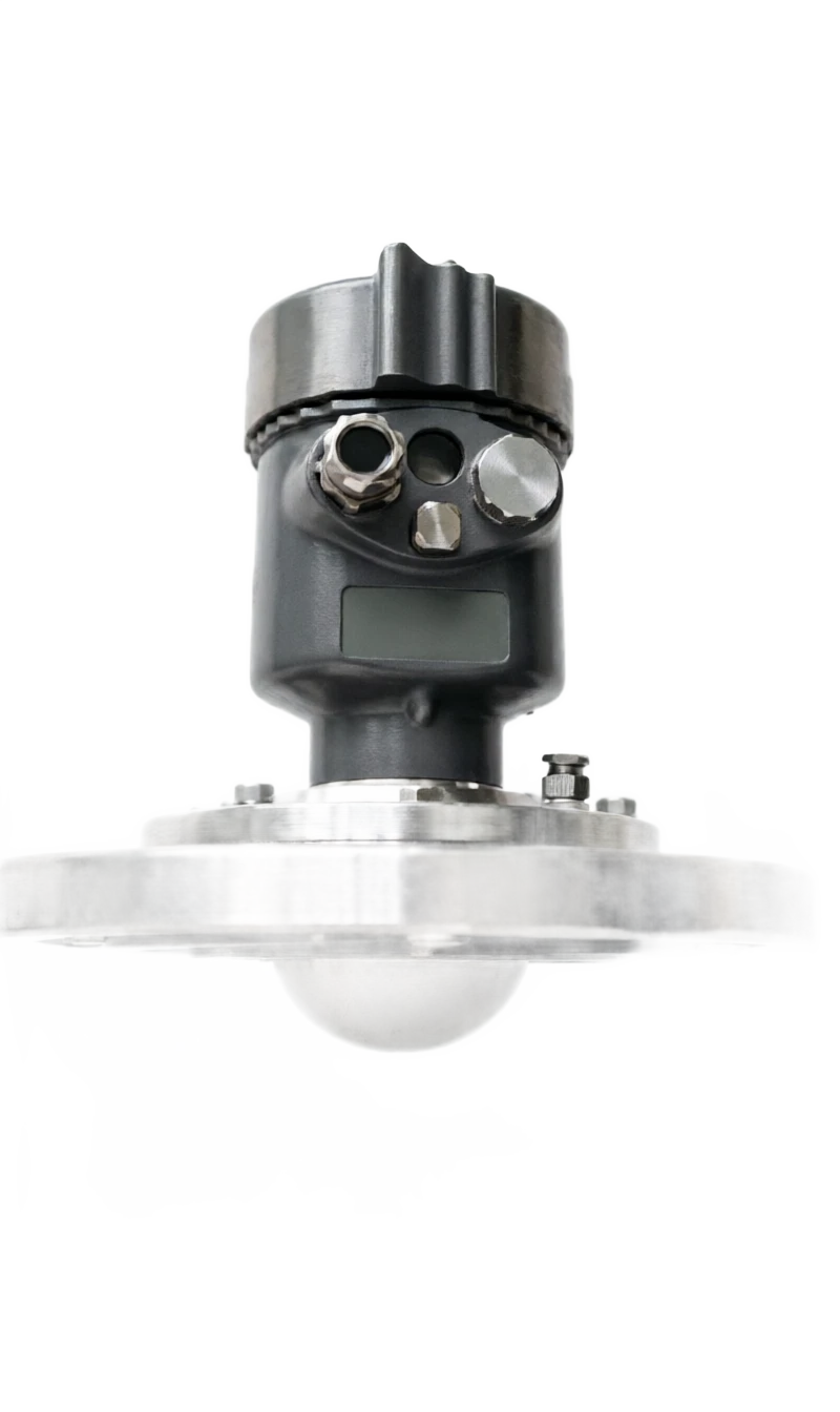
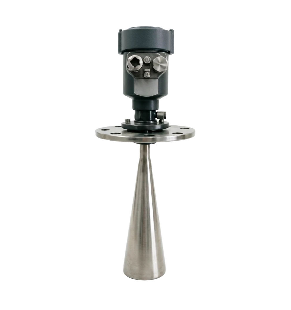
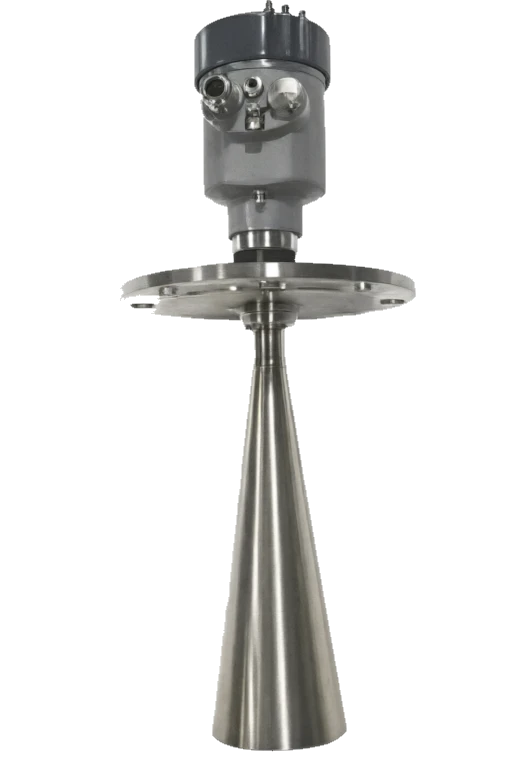
Radar level transmitter

Operating principle

Radar positionometers.

Electromagnetic waves in vacuum or air at speeds of c ⁇ 3 × 10 ⁸m/s。 When radar positionals are sending high-frequency electromagnetic waves to the surface of the detected medium, the electromagnetic waves reflect when they encounter a significantly different medium surface of the ⁇ r medium constant. The echo is received on the same day line and the current mainstream radar position index is used by the FMCW (Frequency Modularized Continuous Wave, FM Consequence Wave) method by measuring transmission time t or phase difference. The distance can be accurately obtained after processing by the VCO. The FMCW programme is highly intervention-resistant, highly accurate and can measure multiple targets simultaneously.

  1. 01

    Pressure oscillator produces continuous wave (usually GHz) with frequency of linear sweeps over time, resulting in frequency deviations after reflection on the surface of the medium

  2. 02

    1~2 ⁇ f; the margin is proportional to target distance and is used by a mixer to rewrite ADC ⁇ FFT

  3. 03

    Radar wave reflex strength is determined by the difference between the medium and the air's medium constant. The larger the medium is measured, the stronger the reflection is measured, the more stable the general pattern: ⁇ r 2 (e.g. oil, plastic particles) is weak and requires a larger antenna and conductor tube; ⁇ r

  4. 04

    εr < >

Radar position tabulation support

Provide survey missions, media and installation conditions and obtain product configuration advice.

Contact us
Radar positionometers Technical note

TECHNOLOGY & APPLICATION

Understand the principles, the exact selection.

From measurement principles to field applications, the technical characteristics and selection elements of radar positionometers are understood.

01

TECHNICAL GUIDE

Overview

(Radar Level Meter, RLM) is a non-contact placeometer that uses electromagnetic waves to reflect on the surface of the medium and to be received by antennas, calculates the distance of the antenna from the surface of the detected medium by measuring the time delay or frequency difference between the launch wave and the echo, and then installs a high-inverse index of the object. Because of their near-independentness to the conditions of medium temperature, pressure, density, viscosity, conductivity, corrosivity, flow, steam, dust, etc., they have become the main programme for high-end physical measurements in the sectors of oil, chemicals, electricity, metallurgical, food, water, etc.

(a) The work bands can be divided into 6 GHz (C-band), 26 GHz (K-band), 80 GHz (W-band), 120 GHz, and four tranches; By measuring principle, it can be divided into FMCW FM serial waves and pulse wave time-time reflections. This summary of 26 GHz/80 GHzFMCW radar, the most common focus industrial site, covers the principles, structure, strengths and weaknesses, areas of application, technical parameters, selection and the full chain of trouble-shooting.

02

MEASUREMENT PRINCIPLE

The working principles (FMCW and pulse waves)

2.1 Basic physical foundations

Electromagnetic waves are transmitted in a vacuum or air at a rate of c ⁇ 3×10⁸ m/s. When the radar position is calculated to send high-frequency electromagnetic waves to the surface of the detected medium, a reflection occurs when the electromagnetic wave encounters a significantly different surface of the medium ⁇ r medium. The echo is received by the same day line, by measuring the time of transmission t or the phase difference

⁇ , can be reached at D:D = c.t / 2 (pulse wave time zone reflection)

D = c. ⁇ / (4 ⁇ f) (FMCW FM continuous wave)

Location L = H - D (H for instrument height, pre-marked)

2.2 FMCW FM Cyclical Waves

The FMCW approach is the current mainstream radar positional indexing programme. The distance can be accurately obtained after processing by the VCO. The FMCW programme is highly intervention-resistant, highly accurate and can measure multiple targets simultaneously.

2.3 Signal transmission path (8 steps)

/Radar LevelMeter, p. 3 Technical summary technical document — Handbook of Options

2.4 Reaction properties and communicators constants

10 (water, acid alkali solution) is a powerful reflection and measures stability.

/Radar LevelMeter, p. 4 Technical summary technical document — Handbook on selection

  1. 01

    Pressure oscillator produces continuous wave (usually GHz) with frequency of linear sweeps over time, resulting in frequency deviations after reflection on the surface of the medium

  2. 02

    1~2 ⁇ f; the margin is proportional to target distance and is used by a mixer to rewrite ADC ⁇ FFT

  1. 01

    Radar wave reflex strength is determined by the difference between the medium and the air's medium constant. The larger the medium is measured, the stronger the reflection is measured, the more stable the general pattern: ⁇ r 2 (e.g. oil, plastic particles) is weak and requires a larger antenna and conductor tube; ⁇ r

  2. 02

    εr < >

Motion of work (FMCW and pulse waves) Serial number / linkCross-reference
Serial numberLinkCritical handling
1VCO Pressure oscillatorGenerate 24~27 GHz / 77~81 GHz linear scan signal
2Power amplification + looperLaunched via antenna; shared with day line
3Media Surface ReflectionThe greater the variance in the commas, the stronger the echo.
4Retard +LNA Zoom inLow noise magnification, weak echo.
5MixerLaunch signal and backwaves get medium frequency ⁇ f
6ADC Sample + FFTDigital signal processing gets distance spectrum.
Motion of work (FMCW and pulse waves) Serial number / linkCross-reference
Serial numberLinkCritical handling
7Revert recognition algorithmFilter interference, recognition of liquid position/interface echo
8D/A Output + Communications4~20 mA / HART / FF / PA / Modbus
Operating principles (FMCW and pulsed radar) · Relative permittivity εᵣ / reflection strengthCross-reference
Media-Media Constant ⁇ rReaction intensityTypical mediumMeasuring difficulty
1.5 ~ 3WeakOil, plastic particles, asphaltHigh, big antenna/traverse
3 ~ 10MediumOrganic solvents, alcohol, foodMedium
10 ~ 80StrongWater, acid, alkalin, salt solutionLow, easy to measure
03

PRODUCT STRUCTURE

Product structure

3.1 List of main components (10 major components)

/Radar LevelMeter, p. 5, Technical Summary Technical Document — Handbook of Options

Shell / End cap

Main function: Secure seal, accommodate circuits, IP67/IP68 Common material: aluminium alloy / stainless steel 316L / plastic

Show Modules

Main function: LCD / OLEED displays measurements, wave shapes, diagnostics Usual materials: glass + PC screens

Microwave module (MMIC)

Main function: VCO Sweep + Mixer + LNA + ADC Integration Usage Usage: GaAs / SiGe Semiconductor

Signal processing MMU/DSP

Main function: FFT, echo recognition, temperature compensation, communication protocol Usual material: ARM Cortex / DSP

Communication interface

Main function: 4~20 ma + HART/ FF/ PA / Modbus Usual Materials: Connector Terminal

Antenna/ lens

Main function: Launch and receive electromagnetic waves, determine beam angles Common materials: 316L / PP / PTFE / PEEK

Process Connecting Frank/ Thread

Main function: Connect to tank / pipe machinery Usual material: 316L / Hapsy Alloy / Line PTFE

Seal O-ring

Main function: Prevent media from entering the instrument cavity Common material: FKM / EPDM / FFKM (Karerez)

Blow-up / Cool-Mechanic

Main function: Nitrogen blowout / Wind cold Usage: 316 L+ interface

Mine/ Wave Control Module

Main function: Mine-proofing, sensory voltage protection

Antenna type

Name of component: Application frequency bands Main function: beam angle Common mass: Typical application Characteristics

Hornet antenna

Component name: 6 / 26 GHz Primary function: 8 ~ 22 % Common materials: liquid, solid silos simple structure, large scale

Bar antenna

Component name: 26 GHz Primary function: ≥20 ° Common Materials: Small caliber packagings, Process Tanks Small enough to fit over DN50

Cable antenna

Component name: 6 GHz Primary function: Full-Use Usage Materials: Long-Link, Well, Liquids up to 100 m Quantum

Mirror antenna

Component name: 80 / 120 GHz Primary function: 3° ~ 8° Common materials: narrow packagings, solid powders Focused, anti-mounted material

flat array antenna

Component name: 80 GHz Primary function: 3° ~ 5° Common materials: small packagings, solid particles Small size, high accuracy

Mounting

Component name: Application of scenes Main function: Quantification Process Usual material: Remarks

Top-package

Component name: Reaction sheet, top of tank, main function: 0~35 m Usual material: most commonly used, beam-down vertically measured

Side-Sack

Component name: Pillow container, side pipe, main function: 0-10 m Usual material: installed through side flange, beam level

Transistor

Component name: Tanks, Narrow Tube, Small ⁇ r Media Primary function: 0-6 m Common Materials: Intra-Piplinic Transmission, Interruptive

Side-to-side pipe

Component name: Strong current, high temperature tank, main function: 0-4 m Common material: measured through side-pipe reflector

External poster (through plastic walls)

Component name: Wall-to-wave scene of plastic tank, main function: 0-10 m Usual material: antennas to external wall, media isolation

04

TECHNICAL GUIDE

Analysis of strengths and weaknesses

4.1 Main advantages

/Radar LevelMeter, p. 6, Technical summary technical document — Handbook of Options

4.1 Main advantages

Non-contact measurements

Note: An antenna is not exposed to the medium, almost without wear and tear, and no congestion

It's almost neutral.

Description: Temperature, pressure, density, viscosity, corrosivity, vapour, small dust effect

High accuracy of measurements

Note: 80 GHz to ± 1 mm; 26 GHz to ± 5 mm

Large scale

Note: Cable up to 100 m, distance 80 GHz up to 150 m

Respond fast.

Note: Typical 1 ~ 3 seconds for rapid change liquid level monitoring

Very low maintenance

Note: No mechanical motion items, long verification period

Strong corrosive, toxic, flammable, explosive mediums

Note: Antenna material optional PTFE / Hapsy Alloy + blastproof authentication

Support for multiple communication protocols

Description: HART / FF / Profibus PA / Modbus / Wireless

Capability for backwave curve diagnosis

Note: Wave shapes are visible, interference and failure are identified

Disadvantages and use restrictions

Price above static / floater

Response: Assessment of recovery period through full life cycle costs (TCO)

Low-media constant medium ( ⁇ r<2) echo weak

Response: Use of conductor tubes / 80 GHz lens antennas

Strong current / foam may be distorted

Response: Loading of conductor tubes / Still wells / Algorithmic filters

Installation is highly demanding

Response: Avoiding feed, mixing, barriers, with reference to 1/3 Cannery Principles

Vapour / Cooled Water absorbs microwave

Response: Increase frequency to 80 GHz or blow-down

Metal barriers produce false echoes.

Response: Segregation through software shielding / transducer

05

APPLICATIONS

Application area

/Radar LevelMeter, p. 7, Technical Summary Technical Document — Handbook of Options

Petroleum chemicals

Typical applications: crude oil, finished oil, feedstock tanks, acid-alkali tanks Recommended frequency band / antenna: 26/80 GHz speakers or poles

Gas and gas storage

Typical application: large stand-alone tanks, trade measurement recommended frequency band / antenna: 26/80 GHz high-precision horn

Electricity / Energy

Typical applications: coal silos, ash silos, plaster salvos, slurry tanks Recommended frequency bands/ antenna: 80 GHz lens antenna

Metal / Steel

Typical applications: high-stove, tar, ore slag Recommended frequency / antenna: 80 GHz lens / plane array

Cement / Building Materials

Typical applications: cement powder bank, clinker bank, feedstock allocation Recommended frequency band / antenna: 80 GHz / cable 6 GHz

Food / Pharmaceuticals

Typical application: CIP tank, syrup, fermenter, feedstock tank Recommended frequency segment / antenna: 26 GHz PTFE Full-sealed antenna

Water / Water

Typical applications: sewage wells, water tanks, rainwater wells, canals recommended frequency bands / antenna: 26 GHz economy

Paper / Chemical

Typical applications: black, green, slurry tanks Recommended frequency band / antenna: 26 GHz + transducer

LNG / Low Temperature

Typical applications: Liquefied Natural Gas, Low Temperature Nitrogen storage tanks Recommended frequency band / antenna: 26 GHz cryogenic

Solid powder / granular silo

Typical applications: plastic granular silos, fertilizer silos, grain silos Recommended frequency band / antenna: 80 GHz / 6 GHz cable

06

TECHNICAL SPECIFICATIONS

Technical Parameter Table

/Radar LevelMeter, p. 8 Technical summary technical document — Handbook on selection

Technical Parameter Table · Parameter Category / Parameter NameCross-reference
Parameter CategoryParameter NameTypical specification
Measuring PerformanceWorking band6 GHz / 26 GHz / 80 GHz / 120 GHz
Measuring PerformanceMeasurement range0~35 m (honor)/ 0~100 m (cable)/ 0~150 m (far 80GHz)
Measuring PerformanceMeasurement accuracy±1 mm(80 GHz)/ ±5 mm(26 GHz)/ ±10 mm(6 GHz)
Measuring PerformanceResolution0.1 mm
Measuring PerformanceRepeatability±1 mm
Measuring PerformanceResponse time1~3 s (modifiable, fastest 0.5 s)
Process conditionsProcess temperature40 ~ +200 ℃ (standard)/ +450 ℃ (with cooling)
Process conditionsProcess pressure1 ~ +4 MPa (standard)/ +40 MPa (high pressure)
Process conditionsMedia-Media Constant ⁇ r≥ 1.6 (weak reflector condition requiring conductor tubes)
Electrical specificationsElectricity voltage16~36 V DC (two-line) / 24 V DC ± 10% (four-line)
Electrical specificationsOutput signal4~20 mA + HART 7 / FF H1 / Profibus PA / Modbus RTU
Electrical specificationsLoad resistance≤ 600 (HaRT)/ 250 (Ben)
Electrical specificationsWork≤ 1 W (biline) / 3 ~ 5 W (team)
StructureAntenna material316L / PTFE / PP / PEEK / Hapsy Alloy C-276
StructureProcess connectionG1 1⁄2/A/B screw, DN50 ~ DN200 François Tri-clamp
StructureShell protectionIP66/IP67/IP68(IEC 60529)
Fireproof.Explosion protection markingEx d IIC T6 Ga / Ex ia IIC T6 Ga
Fireproof.Bomb protection certificationNEPSI / ATEX / IECEx / FM
AuthenticationMeasurement/ CommunicationsHART 7 / FF / Profibus PA / Wireless HART / OCP
EnvironmentAmbient temperature40 ~ +80 ℃
EnvironmentRelative Humidity0~100% RH (cooled condensation)
EnvironmentEarthquake/ Impact ResistIEC 60068 / 4 g Vibration / 25 g impact
07

SELECTION GUIDE

Select Table

7.1 Type by frequency

7.4 Select by Process Connect

/Radar LevelMeter, Technical Summary Technical Document 9 Page Manual Radar Placer/Radar LevelMeter, Technical Summary Technical Document 10 Page Manual

Selecting Table . Code / FrequencyCross-reference
CodeFrequencyWavelengthBeam angleApply scene
RL-66 GHz5 cm22°Large liquid tanks, solid powder, long range
RL-2626 GHz12 mm8°~22°General liquids, mini-responses
RL-8080 GHz4 mm3°~8°Small packagings, solid particles, strong corrosive, narrow space
RL-120120 GHz2.5 mm≤3°Super-shrink, high-precision scene
CodeAntenna typeFrequencySuitable mediaInterface Specifications
AT-HHornet antenna26 / 80 GHzLiquid / SolidDN80~DN150
AT-RBar antenna26 GHzLiquidG1½/G2
AT-CCable antenna6 GHzLiquidDN50 Frank + Heavy
AT-LMirror antenna80 / 120 GHzCorrosive / SolidDN50~DN100
AT-PPlane Array80 GHzSmall packagingsDN50 Flange
AT-WAll sealed PTFE26 GHzCoercion / HealthG1 Health level
CodeApplicationsRecommended frequency bandRecommended antennaRecommended material
SC-01Crude oil / finished oil26 GHzHorn316L + PTFE
SC-02Acid storage tanks26/80 GHzAll sealed PTFEPTFE / PEEK
SC-03Coal / Ashkow80 GHzMirror / Hornet316L + Blowbrush
SC-04Cement powder bank80 GHzMirror / plane arrayAluminium shell + PTFE
SC-05Sewage / Clearing Pool26 GHzHornet / Stick316L
SC-06Food / Fermentation Can26 GHzHealth level316L Mirror polished
SC-07LNG / Cold Cans26 GHzA cryogenic horn.316L + Cold Seal
SC-08Plastic granules80 GHz / 6 GHzMirror / Cable316L
SC-09Vapour / Strong condensation80 GHz+ BrushMirror + Blow-Dry Interface316L
SC-10Slurption / Black liquid26 GHz+ transducerStick + Convey316L + PTFE
Selective Table · Connection Type / SpecificationCross-reference
Connection TypeSpecificationsApply pressureTypical applications
Threaded connectionG1½ / G2 / 1"NPT / 2"NPT≤2.5 MPaSmall response chute, process jar
Flanged connectionDN50 / DN80 / DN100 / DN150 / DN200≤4 MPa / ≤40 MPa High PressureLarge storage tanks
Tri-clamp2 "/3"/4 "Health level≤1 MPaFood / Pharmaceutical / CIP
Conveyor connectionDN40 / DN50 Flange≤4 MPaLow, low, high, high.
Health-level cardboardDIN 11851 / SMS≤1 MPaBeer, dairy products
Range of ⁇ rReflection LevelRecommended programme
εr ≥ 10Strong ReactionAny frequency, any antenna can be measured with stability.
3 ≤ εr < 10Medium ReflectionRecommendation 26/80 GHz + Hornet antenna
1.6 ≤ εr < 3Weak Reflection80 GHz lens / plane array + wave tube must be used
08

SELECTION GUIDE

Selective guidance and trouble-checking

8.1 9 Step Process

/Radar LevelMeter, 11 page, technical summary technical document . Select manual radar positionometer/Radar LevelMeter, 12 page technical summary

Selective guidance and troubleshooting . Step / ContentCross-reference
StepsContentsCritical judgement
1Clearly measure objectsLiquid / Solid / Mulp / Interface
2Verify the relative permittivity εᵣ of the medium.εr ≥ 1.6 , otherwise select high frequency + focus
3Determine the scale and precisionScale ratio 1 : 10 ~ 1 : 100 , Precision ±1 ~ ±10 mm
4Determine process temperature and pressureHigh temperature +450 °C, high pressure 40 MPa requires special specification
5Determine process connectionThread / Frank / Carp/ Health
6Determine antenna formatHornet / Bark / Cable / Mirror
7Set blast/ protection levelEx d / Ex ia + IP67/68
8Establishment of communication protocolsHART / FF / PA / Modbus / Wireless
9Evaluate installation locationsAvoid feed, mix, barrier.
Serial numberAttentionReason
1Antenna centre distance from ≥ 1 / 6 tank pathAvoiding false rebuffs of the cans
2♪ The rims are in the cans ♪Prevent the barrier from being reflected.
3Avoid installation above feed entranceThe feed shock zone is unstable.
4High viscosity / Clearing interface for the slurry mediumPrevention of antennae impact measurement
5High-temperature tank cooled / Insulation tubeProtect electronic parts
6Open-air shieldingUV-resistant, rain-resistant snow
7Sniffed with a sealed raw beltGuarantee IP68 protection
8Metal packagings avoid direct contact with radar cable shield layersPrevent the ground circuits from jamming.
9Mine-protected areas need wave-protectorsProtection of communications interfaces
10Use oscilloscope / HART 475 for debugging to observe wave shapeDiscontinuation of interference echo
Fault phenomenaPossible causeMeasures to address
Measured jumpStrong current / foam / steam / interference echo/ Increase frequency band / algorithm filter
Low measuredAntenna / Condensation / Media ⁇ r lowClean antenna / Increase frequency band / Change to a conductor
High measuredMisidentification of sediment at bottomSet bottom shield / adjust installation position
Selective guidance and trouble-shooting • Fault phenomena / Possible causesCross-reference
Fault phenomenaPossible causeMeasures to address
Show E14 / E17The echo is lost.Check if the antenna is too low, the medium ⁇ r is too low
No display/ Power failure / instrument damageCheck 24V power, load resistance.
Electricity constant 4 MAInstrument into alarm mode (low failure)Check HART fail code
Electricity constant 20 maInstrument into alarm mode (high failure)Check the range settings, back signal.
Interrupted communicationsHART Address Conflict / Bad BlockingReset address, check screen.