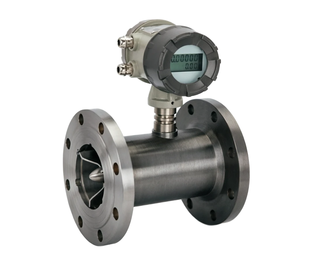
PRODUCT TECHNOLOGY

Liquid vortex rotational measure

Operating principle

The liquid vortex rotational measure.

Turbo blades rotated under a fluid shock, and the fluid volume that was discharged during a week of rotation was a fixed geometry. In ideal cases (frequent frictions and leaks), strict linear relationships between the rotation of leaves n and flow Q within unit time: Q = K n (K as instrument coefficient, in pulse/ m³ or L/p) /LiquidTurbineFlowmeter 3 Pages Technical summary technical document: Selected manual liquid vortex rotationometer/LiquidTurbineFlowmeter 4 Pages Technical summary technical documentation — Handbook on selection

  1. 01

    1 Fluid inflow meters ..to correct the vortex's uneven distribution.

  2. 02

    2 ..shocking the blades ..fluent motion is passed to the wheel, pushing the wheel to rotate.

  3. 03

    3 Leaf wheel steady rotation The speed of n is proportional to the mean flow speed v of the fluid.

  4. 04

    4 . Signal detection . Magnetic resistance/hort/photo/sensitivity detection of leaf wheel movements .

Liquid vortex rotation counter support

Provide survey missions, media and installation conditions and obtain product configuration advice.

Contact us
Liquid vortex rotational measure

TECHNOLOGY & APPLICATION

Understand the principles, the exact selection.

The technical features and selection elements of the liquid vortex rotational meter are understood from measurement principles to field applications.

01

TECHNICAL GUIDE

Overview

(Liquid Turbine Flowmeter, LTF) velocity flow meters based on the constant principle of the kinetic rectangular. When fluid flow is carried through multiple leafy wheels in a pipeline, the fluid impact blade drives the rotation of the leaf wheel, which is n in proportion to the mean fluid flow speed v; The volume flow Q = K.n. can be converted by magnetic or horticultural elements to detect the speed of the wheel.

Because of its high accuracy (%) ±0.5% ) Repetitiveness ( ±0.1% ), Quantification Range () 10 : 1 ~ 30 : 1 ) Respond fast (ms) , vortex rotational meters are used extensively in trade measurement, process control and energy management in the fields of oil, chemicals, electricity, metallurgical, aviation, pharmaceuticals, food, water, etc., and are one of the most accurate mainstream flow meters after the electromagnetic flowmeters and mass flow meters.

02

MEASUREMENT PRINCIPLE

Operating principle

2.1 Basic physical foundations

Turbo leaves rotate under a fluid shock, and the fluid volume that is discharged by a week of rotation is a fixed geometry.

Slight frictions and leaks) , gypsies in unit time n satisfy strict linear relationships with flow Q: Q = K n (K as instrument coefficient, in pulse/ m³ or L/p)

v = q / A (flow speed v = instant flow q / trans-shipment area A)

E = ⁇ dt (cumulative flow E = temporal fraction of instant flow)

2.2 Signal transmission path (8 steps)

/LiquidTurbineFlowmeter, p. 3 Technical Summary Technical Document . Selection Manual Liquid Turmometer/LiquidTurbineFlowmeter, p. 4 Technical Summary Technical Document .

Motion of work . Serial number / chainCross-reference
Serial numberLinkCritical handling
1Fluid inflow metersFluorator flow is complete, eliminating vortex and speed imbalances
2Blasting the turrets.Fluid motion is passed to the wheel, which drives the wheel.
3Leaf wheel steady rotationRotation n positive to flow v of mean fluid speed
4Signal CheckoutMagnetic resistance/Holl/PV/sensor detection of leaf wheel rotation
5Signal shapePre-enlarged, um, integer to standard aerobic pulse.
6CPU ProcessingCalculate instant flow based on instrument coefficient K + accumulation
7Output ConversionD/A Turn 4~20 MA; Pulse Output to DCS / Flow Calculator
8Uploading of communicationsHART / RS485 / Modbus Upper Access
Test MethodRationaleCharacteristicsTypical applications
Magnetic resistanceEternal magnet plus sensor wire, pelt blades of leaves, magnetic wires.Simple structure, no electricityTraditional water/oil measurement
The working principles, the test methods, the principles.Cross-reference
Test MethodRationaleCharacteristicsTypical applications
Hall WidgetHole device detects the rotation of the lobe magnet.High frequency, strong signal.Modern mainstream programmes
PhotovoltagePhoto-to-penetration, wiring of the wiring.High accuracy, no magnetic interference.High viscosity medium
Radio frequency/concealmentCapacitivity change detection of leaf positionFit to non-conductive magnetic environmentSpecial media
SensoryLeaf inner circle, no magnetic designNo magnetic contamination, no interference.LNG/low Electroconductivity
03

PRODUCT STRUCTURE

Product structure

3.1 List of main components (10 major components)

3.3 Typical structure of vortex rotational counters (text description)

⁇ [Signature checker (near magnet + sensor coil)] ⁇ [Exiting French] Liquid Turbo Rotometer/LiquidTurbine Flowmeter 5 page technical summary document ZXA

Shell

Main function: Pressure, accommodater and conductor, determine caliber and pressure level Usage: 316L / Carbon steel / Hapsy Alloy

Import conduits

Main function: Fluiding, elimination of vortex, even distribution of flow speeds Usual material: 316 L / Haps alloy / PTFE

Leaf Wheel Component

Main function: Flow measurement core, multileaf-formation precision processing Common mass: 316L / titanium alloy / Hapsy alloy

Axes + Axes

Main function: to support leaves and wheels; to sustain the bearings with corrosion, low friction, long life; to use commonly used materials: ceramics / hard alloy / tungsten carbonized

Signal Checkout

Main function: Magnetic resistance/hor/photoelectrics, etc., detection of rotational signals Common materials: Permagnet + Sensor coil

Pre-memplifier

Main function: Magnifying the integer to detect a signal as a standard pulse.

Shell Seal

Main function: To prevent leakage of media and stress

Shell / Wirebox

Main function: Protection of internal circuits, IP67/IP68 Common material: aluminium alloy / stainless steel

Smart Converter

Main function: K Coefficient Compensation, Show Time/cumulative Flow Usage Usage: LCD + MMU

Process connection

Main function: Frank / screw / Health-Cardette Usual Materials: GB / ANSI / DIN / Tri-clamp

Classification dimensions

Name of component: Type of primary function: Characteristics Usual material:

Press installation position

Component name: Plumber type (pipe segment) Main function: Direct stringing to process pipe, most commonly used materials:

Press installation position

Component name: Insertion of main function: Inserting large pipe through a ball valve suitable for materials commonly used above DN200:

By pressure level

Component name: General PN16/PN25/PN40 Primary function: General industrial application Usage:

By pressure level

Component name: High pressure PN63 ~ PN160 Primary function: Oil Fields High Pressure Injection, Waters in Wellheads Common material:

Check out the signal.

Component name: Unencumbered Large Primary function: raw weak signal, required with external composer Usual material:

Check out the signal.

Component name: with large main function: output 4~20 MA+ pulse + HART commonly used materials:

Press Media

Name of component: General type Main function: Water, Light oil, Solvent Usage

Press Media

Component name: Low temperature Main function: LNG, liquid nitrogen (-196 °C) Usual material:

Press Media

Component name: High temperature type. Primary function: Thermal oil, steam condensation (+250 °C) Usual material:

04

TECHNICAL GUIDE

Analysis of strengths and weaknesses

4.1 Main advantages

/LiquidTurbineFlowmeter, p. 6, Technical summary technical document. Handbook of selections

4.1 Main advantages

High accuracy of measurements

Note: Accuracy can be achieved ±0.5% R, Repeatability ±0.1% R, tradeable

Wide turndown ratio

Note: Typical scale scale ratio 10:1, high range ratio 30:1

Respond fast.

Note: millisecond response, suitable for pulse flow, batch control

It's a tight structure.

Note: Small size, light weight, easy to install

High pressure resistance

Note: Maximum tolerance 40 MPa, oil field high pressure water injections commonly

Temperature tolerance

Description: Special design tolerance - 196 °C (LNG)

The output signal is rich.

Note: Pulse +4~20 MA + HART/ RS485

Maintenance simplicity

Note: No active parts only leaf wheels, which can be cleaned and replaced on site

Heat can be measured

Note: Some models are measurable +250 °C hot oil

Disadvantages and use restrictions

Sensitivity to fluid cleaning

Response: Pre-filter (20 μm ~ 80 μm)

Not applicable to high viscosity media

Response: Sticky > 30 cSt to remark or select other instruments

Need to have a straight line.

Response: Former ≥ 10 D, post ≥ 5 D bending or valves

Axes wear and tear affect life expectancy

Response: Select rigid alloy bearings to be maintained regularly

Pulse flows cause errors.

Response: Buffering tanks or fluorators are added to the front

K coefficient affected by viscosity

Response: Smart transporter with viscosity compensation

Not applicable to gaseous phase

Response: Ensure that the pipes are full and that they are mono-streamed

Prices higher than electromagnetic flowmeters

Response: offset by precision advantages and trade settlements

05

APPLICATIONS

Application area

/LiquidTurbineFlowmeter, p. 7 Technical summary technical document . Handbook of selections

Oil / Gas

Typical applications: crude oil, finished oil, trade measurement of liquefied gas, recommended model / specification: DN50 ~ NN300 high pressure type

petrochemical / chemical plant

Typical applications: feedstock, solvent, intermediate transport Recommended model / Specification: DN25~DN200 Generic

Electricity / Energy

Typical applications: fuel, condensed water, water flow recommended model / Specification: DN50~DN150 high temperature

Chemical/ pharmaceutical

Typical applications: process materials, raw material liquids Recommended model / Specification: DN10~DN100 Health type

Metal / Steel

Typical applications: cooling water, hydraulic cycle, recommended model / specification: DN80 ~ NN300 large caliber

Aviation / Space

Typical application: fuel, propellant injections Recommended model / Specification: DN10~DN50 High precision

LNG / Low Temperature

Typical applications: LNG, LNA, LOS, Recommended Model / Specification: DN25~DN200

Food / Beverage

Typical applications: syrup, juice, edible oil fillings Recommended model / Specification: DN10~DN80 Health level

Water / Water

Typical application: water purification, pure water distribution measures Recommended model / Specification: DN50~DN300 Economic

Ship/ Seafarers

Typical applications: fuel, oil skiing, freshwater systems Recommended model / Specification: DN25~DN200

06

TECHNICAL SPECIFICATIONS

Technical Parameter Table

/LiquidTurbineFlowmeter, p. 8 Technical summary technical document . Handbook of choice

Technical Parameter Table · Parameter Category / Parameter NameCross-reference
Parameter CategoryParameter NameTypical specification
Measuring PerformanceCalvary rangeDN10 ~ DN600(1/2″ ~ 24″)
Measuring PerformanceAccuracy class±0.5% R / ±1.0% R (trade class ±0.25% R)
Measuring PerformanceRepeatability±0.05% ~ ±0.1%R
Measuring PerformanceTurndown ratio10:1 (standard)/20:1 / 30:1
Measuring PerformanceFlow velocity range0.3 ~ 10 m/s (standard); 0.1 ~ 5 m/s (low current speed)
Process conditionsProcess medium temperature196 ~ + 120 °C (standard); maximum + 250 °C (high temperature)
Process conditionsProcess pressurePN16 / PN25 / PN40 / PN63 / PN100 / PN160
Process conditionsMedium viscosity≤ 30 cst (standard); ≤ 200 cst (high viscosity)
Process conditionsMedium cleanlinessPre-filter required, filter accuracy 20~80 m
Electrical specificationsElectricity voltage12~36 V DC / 24 V DC ±10%
Electrical specificationsOutput signalPulse (frequency)+4~20 ma +HART/ RS485 / Modbus
Electrical specificationsPulse Equivalent1 L/p ~ 1000 L/p (setable)
Electrical specificationsWork≤ 0.8 W
StructureHousing material316L / Hapsy Alloy C-276/ titanium / PTFE liner
StructureImpeller material316L / titanium alloy / Haq alloy
StructureBearing materialCeramic / Cyclops / hard alloy
StructureProcess connectionFrançois GB/ANSI/JIS, screw, sanitary cardboard
StructureShell protectionIP66 / IP67 / IP68
Fireproof.Explosion protection markingEx d IIC T6 Ga / Ex ia IIC T6 Ga
Fireproof.Bomb protection certificationNEPSI / ATEX / IECEx / FM / CSA
AuthenticationTrade settlementCAS Metrology Type Approval + JJG Metrology Protocol
EnvironmentAmbient temperature40 ~ +70 ℃
EnvironmentEnvironmental humidity0~95% RH (no condensation)
07

SELECTION GUIDE

Select Table

7.1 Type by caliber and flow

/LiquidTurbineFlowmeter, p. 9 Technical Summary Technical Document . Selection Manual Liquid Turbometer/LiquidTurbineFlowmeter, p. 10 Technical Summary Technical Document .

Selective table . Code / caliberCross-reference
CodecaliberCommon Flow Range (m³/h)Apply scene
TF-15DN150.4 ~ 6Small flows, experiments, fillings.
TF-25DN250.6 ~ 12Add, refill, process control
TF-40DN401.5 ~ 30Small and medium-size flow of raw materials
TF-50DN502.5 ~ 60Common industrial pipelines
TF-80DN806 ~ 150Control Line Flow
TF-100DN10010 ~ 250Industrial Director Line
TF-150DN15020 ~ 500Big traffic lead line
TF-200DN20040 ~ 1000Oil out of the pipeline, circulatory water
TF-300DN30080 ~ 2000Water supply, fire water
TF-600DN600300 ~ 8000Large-calibre trade measurement
CodeApplicationsPrecision requirementsRecommended Specifications
SC-01Measurement of crude oil trade±0.25%RDN100~DN300 Pressure +CA
SC-02/ Lightweight oil±0.5%RDN50~DN200 Generic
SC-03Liquefied Gas / Lamp±1.0%RDN25~DN100 Temperature
SC-04LNG raise±0.5%RDN15~DN50-196°C cryogenic
SC-05Water / Clear±1.0%RDN50~DN300 Economy
SC-06Hot oil / hot oil±0.5%RDN50~DN150 High Temperature +250°C
SC-07Chemical solvents±0.5%RDN25~DN100PTFE liner
SC-08Food / Pharmaceuticals±0.5%RDN10~DN80 Health level 316L
SC-09High pressure water (oil fields)±1.0%RDN50~DN200 PN63~PN160
SC-10Hydraulic oil cycle±0.5%RDN25~DN100 High Pressure Type
Sticky rangeRecommended ModelK Coefficient Compensation
≤ 1 cst (water purification, gasoline)Standard TypeNo compensation.
1 ~ 5 cst (light oil, alcohol)Standard TypeWeak impact
Selecting Table . Sticky Range / Recommended ModelCross-reference
Sticky rangeRecommended ModelK Coefficient Compensation
5 ~ 30 cSt (diesel, crude oil)Sticky Compensation TypeNeed for viscosity compensation
30 ~ 100 cst (prissile oil)High viscosity typeRemark to be remarked
> 100 cst (heavy oil)Not recommendedConsider mass flow meters or electromagnetic flowmeters
caliberPN16PN40PN63PN100PN160
DN25
DN50
DN80
DN100—
DN150——
DN200———
DN300———
DN600————
08

SELECTION GUIDE

Selective guidance and trouble-checking

8.1 9 Step Process

/LiquidTurbineFlowmeter, p.11 Technical summary technical document . Selected manual liquid vortex rotationometer/LiquidTurbineFlowmeter, p.12 Technical summary

Selective guidance and troubleshooting . Step / ContentCross-reference
StepsContentsCritical judgement
1Clear media and performanceLiquid type, viscosity, cleanness, temperature, pressure
2Defining the range of flowsMinimal/maximum flow ⁇ caliber (flow speed 0.3 ~ 10 m/s)
3Determine precision requirementsTrade level ±0.25% / Industrial level ±0.5% / Economic level ±1.0%
4Set pressure levelPN16 ~PN160 by Status
5Determine process connectionFrank specification, screw, cardboard.
6Confirm signal checkoutMagnetic resistance/ Hall/ Photoelectric/ Sensor
7Determination of blast-proof requirementsEx d / Ex ia、NEPSI / ATEX
8Determine OutputPulse +4~20 ma +HART/ RS485
9Save filter + direct line segmentFormer ≥ 10 D/ Post ≥ 5 D
Serial numberAttentionReason
1Keep it flowing.To prevent the gas from mixing into error.
2Former ≥ 10 D/ Post ≥ 5 D direct segmentKeep the flow steady.
3Former ≥ 20 D Add FluoratorErase the vortex.
4Pre-filter (20~80 μm)Prevention of wear and tear of leaves
5Stay away from vibrating sources.Prevent extra wear and tear on the bearings.
6Horizontal pipe: flow count level or axisPrevention of sediment accumulation
7The arrows are the same as the process.Make sure you're measuring correctly.
8Avoid approaching the pump exit.- To prevent a pulse flow error.
9It's forbidden to cross-square gas.K coefficient completely invalid
10We have to mark the current before we ship.Eliminate installation errors
Fault phenomenaPossible causeMeasures to address
Show no flowYew Cage Dead / Break / Filter BlockDismantling of leaves, replacement of filters, inspection of connections
Large flowLow K-factor / worn impellerRe-profiling, inspection of the leaves wheel
Small trafficK coefficient high / axle bearing wearRe-profiling, replacement of bearings
Selective guidance and trouble-shooting • Fault phenomena / Possible causesCross-reference
Fault phenomenaPossible causeMeasures to address
Flow JumpPulse flow / Gas fluids / InterferenceBuffer tanks, flowers, gas-excised.
Increase Errorviscosity change / mudslides / corrosiveCleaning, re-marking
No output signalPre-magnification damage/ wiring errorCheck 24V power supply, change amplifiers.
Cumulative deviationPulse lost / coefficient driftCheck shield, check factor