
PRODUCT TECHNOLOGY
Glass rotor flow meter
Operating principle
The glass rotor flow meter. The working principles.
(b) Flow measurements in a variable area: Flow size is reflected by changes in circulation area (i.e., float height) in the area of circulation by the channel of circulation of the cone and the float, which varies with the flow, and the differential pressure formed before and after the float remains essentially constant. The measurement component consists of vertically installed conical glass tubes (upwards) and built-in floats, with the medium moving down to the cone tube: (P₁ - P₂) A_f = V_f ( ρ_f − ρ ) g + F_v where: - P₁ - P₂ - float up and down (approximate constant); - A_f — maximum cross-section area of floats; - V_f, old_f — float volume and float material density; - Old - Medium
- 01
(b) The fluid flow produces a throttle at the loop between the float and the cone, and the floats form a differential pressure at both ends;
- 02
The differential pressure acts to generate upward thrusts of the float, which drive the float to rise;
- 03
(b) Increase in circulation and decrease in differential pressure in circular areas following floats ' rise;
- 04
When the float is balanced by the upward strength of the float with the gravitational force of the float, the floating and viscosive strength of the float-opening medium and the adhesive force, the float stabilizes at a certain altitude;
Structure
• Structured composition
Brush connections (fast plugs), metal screw connections (G inner screws), French connections (GB/T 9119), sanitary card swirling - choice by caliber and condition.
- 01
Conical glass tubes • Corbinthium silicon glass, vertically mounted on the main end, and flow-stamping (gas/liquid double tics or custom ruler) on the outer wall
- 02
Float (rotation) 304 stainless steel (ordinary), PTFE/tetrafluoride (povability), plastic (micro); common shapes are cone, spherical, disc-shaped, float with tilted troughs stable, readable
- 03
Base/link 304 stainless steel (ordinary), cast iron; embedding internal liner PTFE
- 04
Seal seals Fluorine rubber, tetrafluorosulphuride gaskets
Application area
Glass rotor flow meters . Application area
Typical use location: a constant pressure temperature clean media event with "reading through and approximate flow" and no measure of settlement. Not applicable: Flammable risk zone (replacement of metal pipe floats), high pressure (>1.0 MPa) pipe, strong vibration scene, high viscosity (>50 mPa.s), particle/feasible medium, non-transparent medium, automated system requiring remote signal (replacement of metal pipe float or electromagnetic flowmeters).
- 01
Laboratory/scientific & T & P, laboratory ratio, analytical instrument kit (maximity scene)
- 02
Water treatment/environmental protection Measurement (condensant, disinfectant), small exposure, monitoring of sampling flow
- 03
Chemical/oil/fertilizer/fibre Monitoring of low-pressure secondary road processes, visual reference of traffic of nitrogen-blowing pipes
- 04
• Monitoring of the constant pressure of low-compulsive medicine, distribution secondary roads (non-sanitary level)
Selection Guide
Glass rotor flow meters . Selective guide
(b) The principle of metrology matching: the common flow falls on the 40% ~70% zone of the full range with the smallest error; When the liquid is very viscous or is significantly different from the density of the rated medium, the manufacturer is required to customize the ruler to the actual medium. Example: LZB-15F - Water-Specific Scale = Corruptorproof Glass Rotometer, DN15, customizing water scales to the user medium.
- 01
(b) Safety red line: blast-proof area, high pressure, strong vibration, water hammer work is always conducted without a glass rotor flow meter, and the metal pipe float flow meter is selected directly (the long-range model also allows output of 4-20mA);
- 02
(a) Media conversion: the density, viscosity, and modulation by the manufacturer when ordering non-water/air media; the medium in use is subject to recalculation if the conditions of the medium vary significantly;
- 03
(b) Filters: Y-type filters are added upstream when the medium contains particles to prevent the death of the float;
- 04
Operating norms: full upstream valves slowly on start-up, fine-tuned downstream valves to control flow; stop-off to turn up the upper valves and then to close down the valves; full upper valves at gas measurement and by the lower valves to regulate;
Model Selection SELECT A MODEL
1 Model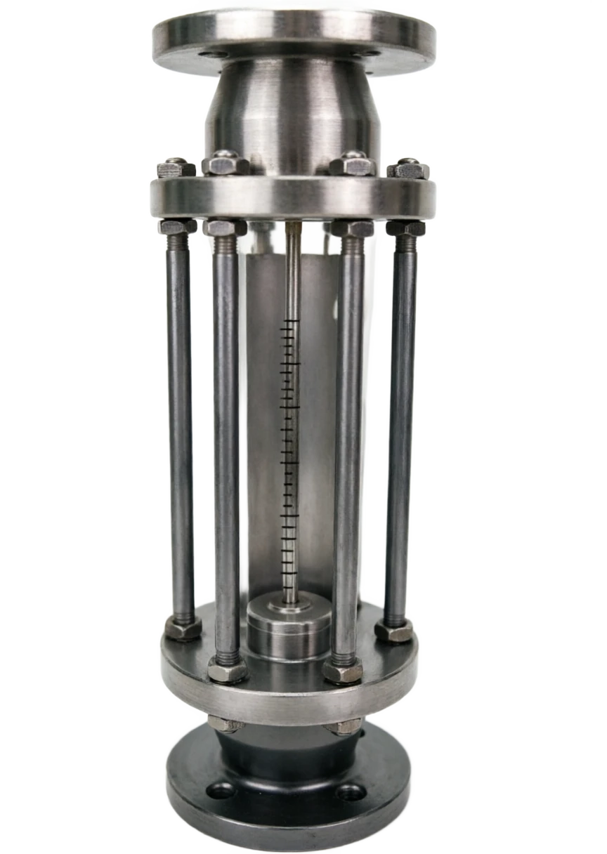
Glass rotor flow meter support
Provide survey missions, media and installation conditions and obtain product configuration advice.
Contact us