
PRODUCT TECHNOLOGY
Smart Flow Impressor
Operating principle
Smart flow compute.
(a) The core structure of "flow signal acquisition + compensatory operation + time accrual + cumulative maintenance": traffic channels (simulation or pulse) are taken together with compensation channels (temperature, pressure) and MMU calculates instant flow (mass flow or standard volume flow) using the selected media model to accumulate the instant flow points in the fixed crediting cycle (typical 1-2s) and write the volume into EEPROM to keep the discharge; (c) A batch machine with a material control logic and a trade machine with audit records.
- 01
1 Flow signal input • Simulation channel: differential pressure 4-20mA (indoor open-side flow, precision limited by simulation link); Pulse / Frequency channel: Turbo Street / Turbo / electromagnetic pulse (0~10kHz), photometric isolation count, instrumentation factor K (pulse / l) group - highest cumulative accuracy path
- 02
2 • Compensatory signal input • Pressure channel: 4 - 20mA / voltage (insulation or pressure group); temperature channel: Pt100 / Thermal electromechanical doll/ 4 - 20mA ; three-channel synchronized sampling ensures consistency of compensation
- 03
3 Media model calculations • Saturation vapour: pressure or temperature single parameter density; Overheating vapour: temperature double-parametric table (IFC formula); General gases: ideal gas + compression factor correction; Gas: a component or standard compression factor (AGA8 / SY/T); Liquid: density setting or temperature correction
- 04
4 . Time flow calculation . differential: q = K x sqrt (x old); frequency: q = f / K x old (K for instrument coefficients); small signal removal (< 5% FS zero to prevent accumulation of absindation); resistance to nitro smooth fluctuations
Structure
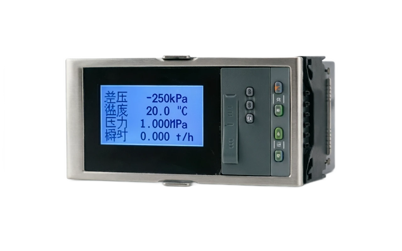
Smart flow composer. Structured composition.
The whole machine is embedded in the panel structure, which is dominated by 96 x 96 mm (general) and cross-section 160 x 80 mm (double channel/ trade, with more digits shown), with multiple digital displays and buttons on the front plate, cores consisting of the master control plate and input output plate, and pulse separation and power loss to keep the circuits the focus of the hardware design.
- 01
1 . Front panel multi-digit LED display: instant flow + cumulative amount (8 ~ 12 bit) + compensatory parameter switch display; batch stop / double / zero key (lock with permission); status light (run / batch / ton/ alarm)
- 02
2 Input plate . Simulation input: flow differential / pressure / temperature channel (ADC); pulse input: light rim-separated high-speed counter (0-10 kHz); input type group switching
- 03
3 Master Board · MMU run media model and accrual logic; models and parameters EEPROM; RTC clock (class/ day/ month cumulative report item count)
- 04
4 • Power outage to keep circuits • Super-capable / small battery buffer failure writing; cumulative EEPROM partition double back-up (bad block redundancy); time stamping of power out events
Application area
Smart flow calculator . Application area
The typical industry distribution is as follows:
- 01
• Heat-replacement steam-in-house measurement, heat-remission (cooling) settlement, single net/drive water • superheated steam compensation / heat machine + printing report
- 02
Petrochemicals · Inter-facility Vapour / Nitrogen / Compressed Air Measurement Test, Carload Quantification, Bulk Control Type + Double Channel + Modbus
- 03
Gas / Business user gas measurement, voltage container measurement + gas component correction + temperature compensation + audit
- 04
Electricity Boiler gas supply, energy balance measurement at plant level, gas for devulcanization & gas & saturation steam sheet parameters
Selection Guide
Smart flow calculator . Selecting guide
The complete description shows the technical sections.
Model Selection SELECT A MODEL
1 Model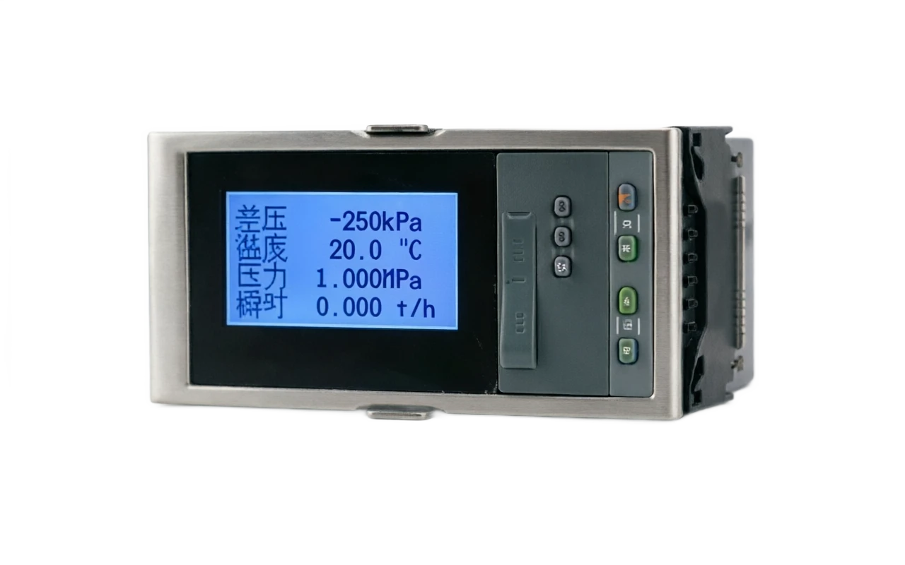
Smart flow calculator selection support
Provide survey missions, media and installation conditions and obtain product configuration advice.
Contact us