
PRODUCT TECHNOLOGY
Smart Digital Flash Alert
Operating principle
Smart digital flash alarm.
(a) A core structure with "multi-road input sample + alarm status machine + digital scintillation display + hierarchical sound + software configuration": switch-point sampling with (optional) analogue input cycle, flow of each route by alert status (alert/ confirm/ restore/revert), digital tube flashing at alarm time of occurrence indicating alarm circuit number (highest priority unrecognized alert), synchronised light flashing of light windows, and a hierarchical hint of sound; Confirms that the digital turnover is displayed and the unreverted return path is rotated, all events are timescaled and can be sent via RS-485.
- 01
1 • Regular surveillance • Digital display of clocks or patrol rounds; lights out; no sound • All entered in non-alarm state
- 02
2 • Digital flashing indicates the circuit sign (the highest priority is shown when multiple paths are not confirmed); light flashes; accident-grade sound; input point action or simulation limit
- 03
3 Run confirmation (disappearing) . Sound is completely eliminated; numbers continue to blink the loop sign . Press confirmation (disrupting) button
- 04
4 Sub-Alarm Queue . Confirmed return route flat; new callback take-over flashlight.
Structure
Smart digital flash alarms. Structured composition.
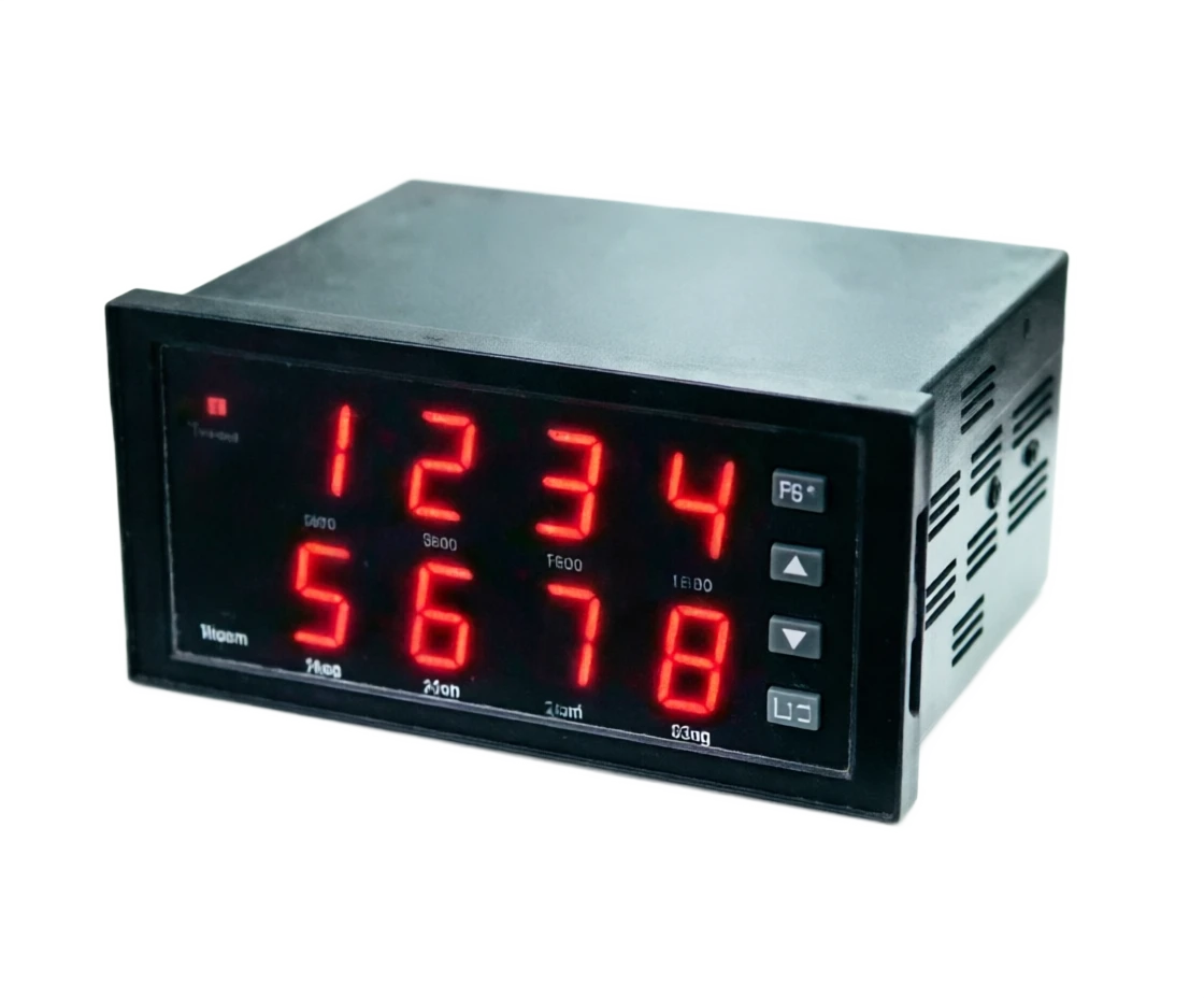
The whole machine is embedded in a panel structure, dominated by 96 x 96 mm (main) and 80 x 160 mm (wideband display), with two rows of the front plate digital + light window (or light column) + confirmation / double / test buttons, cores consisting of input plates, master control panels and sound units, and platform design (conforming with appearance and group tools).
- 01
1 . Two rows LED digital (main row alarm/ bit, sub-row value/ time); light window or light column (by turn-off); confirmation (blowing)/ double / test button; group key (password entry)
- 02
2 Switching Volume Input Panel 8~32 Pathpoint End; Query voltage Output; Photolink Isolation 1500V; Open and Closed-by-Wide Software Group
- 03
3 Simulation volume input boards (optional) · 4-20mA / Pt100 / Thermal electromechanical channel; upper- and lower-limit alarm computing engine; integrated access to alarm arbitration with switch volumes
- 04
4 . Master Board . MPU Status Machine + Priority Arbitration + Display Drive; Group Parameters and Event Record EEPROM; RTC Clock (incident timescale)
Application area
Smart digital flash alarm . Application field
The typical industry is distributed as follows:
- 01
Hot-to-heater · Small and Medium-Sized boiler Room Warning Wall Replacement (Page 58 XXS replacement); Airbag Water Level (Page 57 node) + Overpressure + Fire out + Simulation Water Level Value + Screen + + Simulation Mixed Input + Level Sound + Extraring Bell
- 02
Chemical Chemicals • Independent alarm cabinet (safe-deep outside DCS); storage tank liquids high / low + temperature warning; gas alarms double tip + RS-485 + separation fence transposed
- 03
Water treatment / pumping station Pump failure + pool fluid level + simulated volume pressure indicates alarm; unmanned station alarm box + 24VDC + constant input + touch drive sound tower
- 04
Metallurgy building materials • Temperature of the furnace (simulation upper and lower limits) + burning point alert; kiln cooling water break • Simulation input type + graded tip + event recording
Selection Guide
Smart digital flash alarm . Selecting guide
The complete description provides a view of the technical sections.
Model Selection SELECT A MODEL
1 Model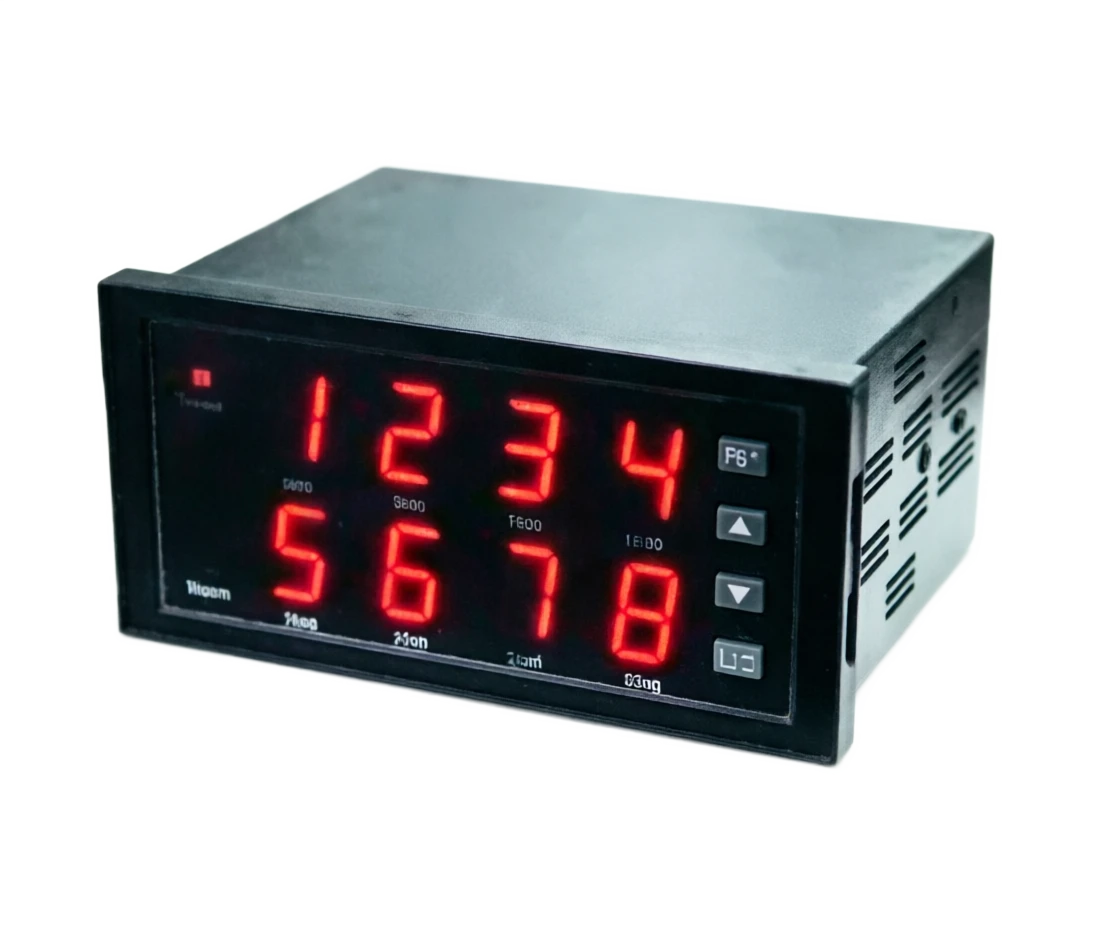
Smart Digital Flash Alert Selection Support
Provide survey missions, media and installation conditions and obtain product configuration advice.
Contact us