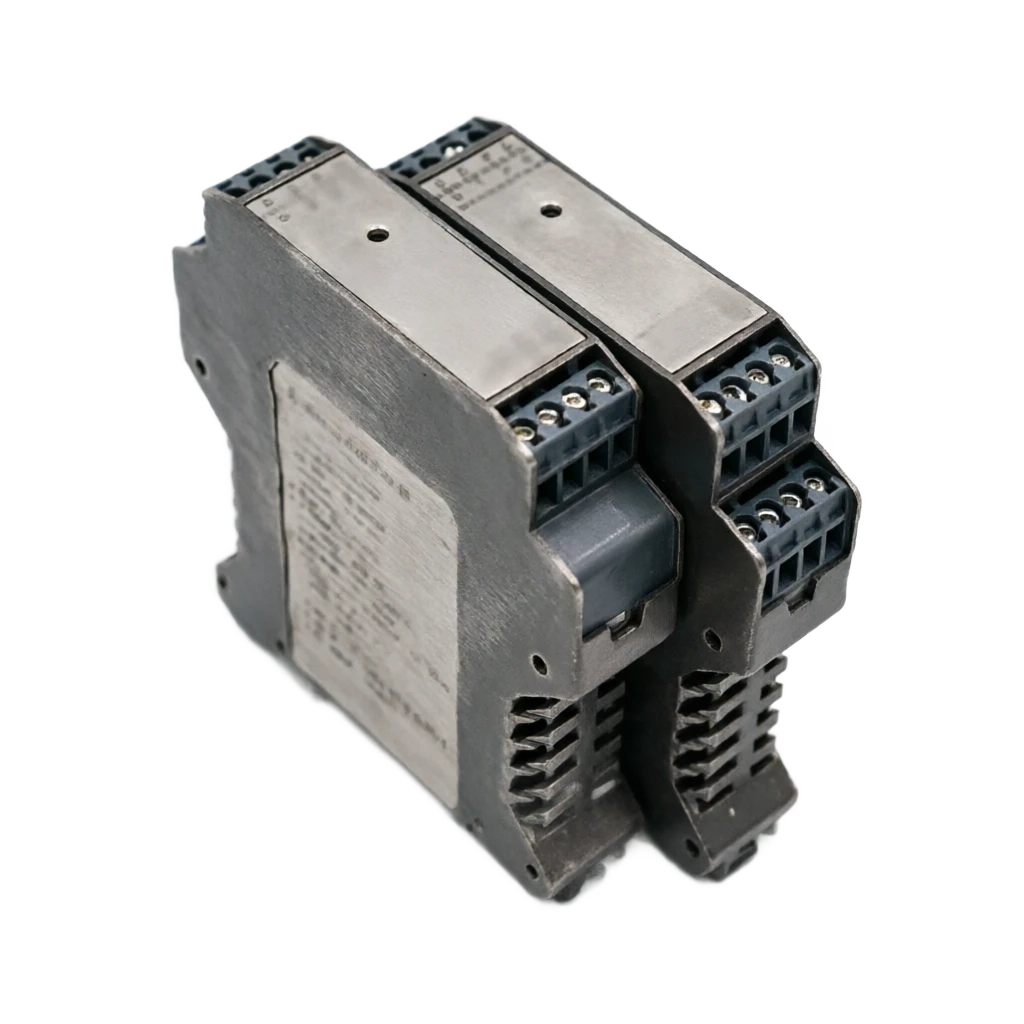
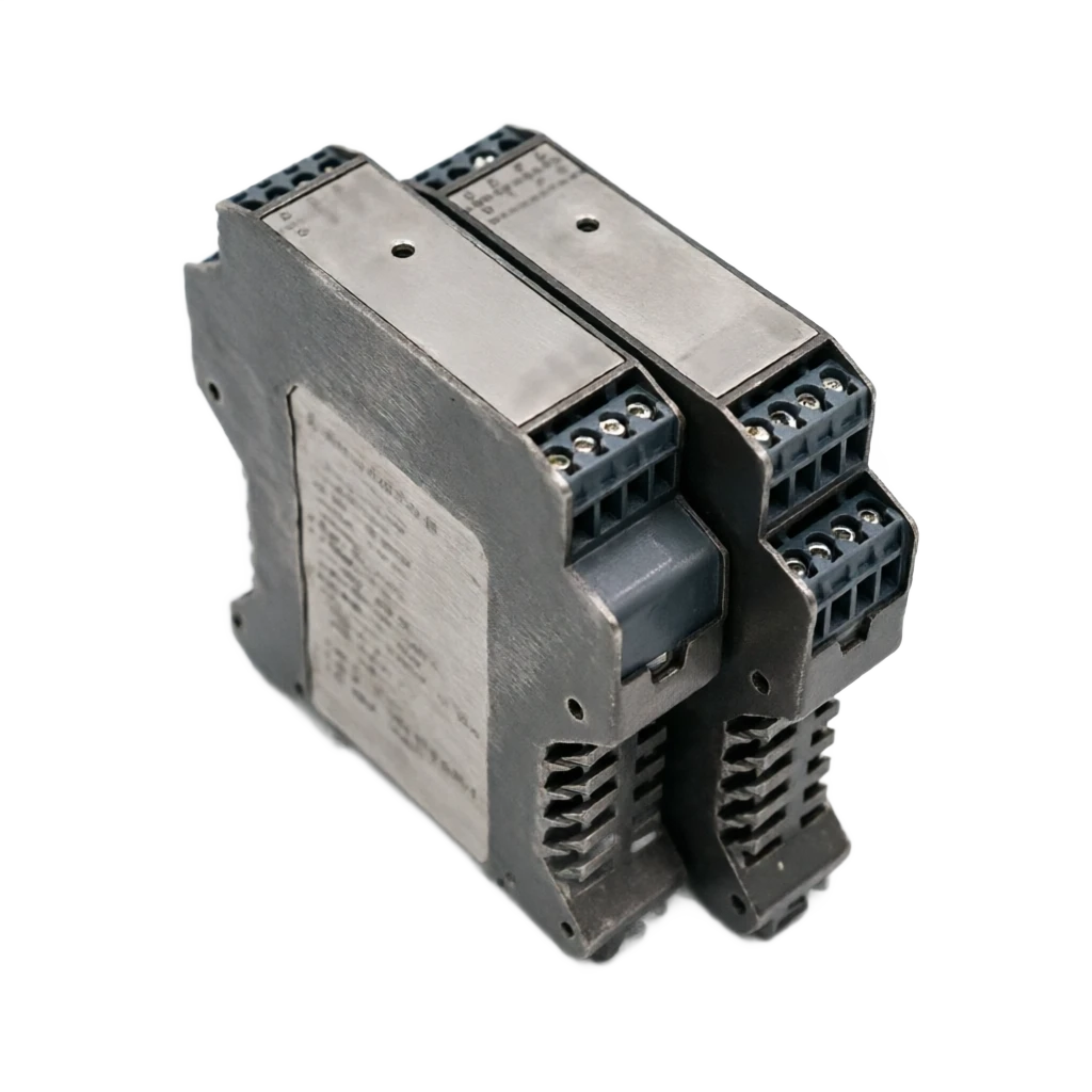
PRODUCT TECHNOLOGY

12V/45mA driver, switch output separation fence

Operating principle

12V/45mA drive, switch output separation fence

The working principle of the switch output fence revolves around a three-part chain of "control side signal reception ⁇ quarantine transformation ⁇ side side of the site with a limited energy drive". This section is based on the three angles of "control side inside the fence inside the field side" and ends with four key calculations of "NAMU standard judgement + 12 V/ 45mA Ben Five Parameters + fail safety mode + short-circuit protection time series". Controlled signal reception in multiple modes of output compatible with DCS/PLC -1 24 V relay point input: dry point closed trigger, threshold voltage 5 ~ 15 V, Corresponds to Logic 1 " Efficacy; The cut-off is considered to be "logical 0". ② 24 V Transistor input (PNP/NPN): PNP high-altitude effectiveness (PNP) 2

  1. 01

    2 Internal fence: DC/DC floating + Isolator transformer + smart limit

  2. 02

    Active status ("1) I > 1.2 MA (typical > 2.1 MA) U > 8 V . On-site device trigger; DCS reading "Logical 1"

  3. 03

    Short-circuit protection . I ≤ 45 mA U down to ≤ 1 V. Short-circuit restricted flow; automatic diagnosis of the fence

  4. 04

    Break-through detection. I. < 0.1 mA · U ≥ 12 • Cable breakers; trigger alarms

12V/45mA driver, switch output separation fence support

Provide survey missions, media and installation conditions and obtain product configuration advice.

Contact us
12V/45mA driver, switch output separation fence

TECHNOLOGY & APPLICATION

Understand the principles, the exact selection.

From the measurement principle to the field application, the technical characteristics and selection elements of the switch output fence are understood as 12V/45mA-driven.

01

TECHNICAL GUIDE

Overview

1.1 Product definition and attribution

Switch output fence (hereinafter referred to as "Treasure output fence" or "DO separation fence") is a device installed in the safe zone control room (DCS/PLC digital output card, relay output plate, transistor output panel)

On-site station-based equipment with hazardous areas (NAMU near switch, Ben An electromagnetic valve, audio alarm, speaker, electronic horn, Ben An LED light)

Essentially secure interface equipment between the two, with four tasks

On-site side energy (detonation), control side separation (anti-disruption), signal conversion (24V switches ) 12V/45mA, fault protection (short/open).

In the Industrial Process Automation Pyramid, the fence is located on the floor of the on-site equipment (Ben EMP/NAMUR approach switch/alert)

Between the control layer (DCS/PLC), the core member of the "Closure Output End" of the Backway Interface family.

Its "12V/45mA" feature follows strictly the IEC 60947-5-6 (NAMUR) standard-- the output voltage model 8-12V, short-circuit current cap 45MA, which corresponds to the direct drive of the Zone 0/1 ira/ib level of the Ben An electromagnetic valve, NAMU approach switch, acoustic alarm.

1.2 Family division of labour

1.3 Three paragraphs of the development history

(1) Relays direct repulsion (1980s)

DCS switches are directly driven by relays and are free of isolation and limited to simple applications in non-hazardous areas.

(2) Zina Fence Period (1990s~2000s)

Use the Zina 2-Code limit plus level-to-place to achieve Ben-Ann, and require grid-to-wire resistance. ≤ 1 Applications are limited once and cannot be used in situations where there is a ground failure of electricity.

(3) Detonator isolation period (2010s~)

DC/DC floating + isolation transformer + intelligent limit, no equivalent level of electrical access requirements, and significant increase in reliability; NAMUR NE 044 (IEC 60947-5-6) standard harmonization 8V/1mA Effective, 12V/45mA Short-circuit Power Flow caps, with representative products such as P+F KFD2-SR, MTL 3300/4500, PR electronics 5104/5106, etc.

1.4 Relationship to Part 64/71/73

Title 64, Separated Safety Fence, is a generic overview covering all categories of detection end, control end, temperature end, switch end; Part 71, Input Detection Screech, is the depth of its 4-20mA input detection branch; Title 73, "Schemble RTD/TC separation fence", is the depth of its "temperature programmable" branch; This is the NAMUR 12V/45mA drive depth of its "Close-outend" branch. Four are "general detectability temperature output" "four track 64" generic items for "doing everything"; 71 For "Separating + Measuring" carrier circuits; 73 For "Unable input + remote group" temperature circuits; This is for the 12V/45mA Ben-Drive Switch Output Return Path.

General · Membership / DutiesCross-reference
MembersDutiesCorresponding scene
Switch output fence (this page)DCS switch signal ⁇ 12V/45mA Ben-Ann driveNAMUR Approach Switch / Bennen EMP/ Alarm
Part 64 Segregated Security Fence (General-Present)Cover all items of detection/control/temperature/maskGeneric project type-selection
Part 71 Input detection fence (4-20mA)Specialise in second-/ fourth-line transvestite 4-20mA input testingSecond-line transmitter distribution + detection
Part 73 Programmable RTD/TC Separation FenceRTD/TC altruistic input + remote groupingMultisensor Mixer + Retrofit
Switch input fence (to be expanded)On-site NAMUR/ Drypoint DCS inputLive switch signal acquisition.
Zina security fence (alternative)Zina D.C. + P.O.T.Traditional programmes, with reliable land-based systems
02

MEASUREMENT PRINCIPLE

Operating principle

The working principle of the switch output fence is to move around the three links of "control side signal reception ⁇ quarantine transformation ⁇ side side of the site with a limited energy drive". This section is based on the three angles of "control side inside fence inside fence inside site side" and ends with four key calculations of "NAMUR standard judgement + 12V/45mA Benne Five Parameters + fail safety mode + short-circuit protection time series".

2.1 Control side: Signal reception and electrical level conversion

The control side consists of two essentially related tasks.

Control of signal reception and electrical conversion.

Controlled signal reception in multiple modes of output compatible with DCS/PLC -1 24 V relay point input: dry point closed trigger, threshold voltage 5 ~ 15 V, Corresponds to Logic 1 " Efficacy; The cut-off is considered to be "logical 0".

② 24 V Transistor Input (PNP/NPN)

PNP High Level Effectiveness (24 V ⁇ Logic 1), NPN Low Level Effectiveness (0 V ⁇ Logic 1), fence end recognition via PV coupling.

③ 5 V TTL/CMOS level

Low-capacity signals, which need to be pushed up to 24 V internal logical level, with high bandwidth radials to ensure the integrity of the signal.

Reverse logic (power failure is safe)

The DCS output should be "logic 0" when power is out, and the on-site device is off -- this is mandatory for the SIL grade circuit.

  1. 01

    2 Internal fence

    DC/DC floating + Isolator transformer + Smart-limited flow

The fence is made up of four parts.

1 Photovoltaic coupling input - side of control 24 The V signal is inside the fence. 5 V TTL Logic, Separatizing Pressure ≥ 1500 Vrms; 2 MPU + Logical Control - Execute Inverted 10 ~ 50 ms tremors, logical reverses, fault diagnosis, high-end machine support for HART communications and state feedback; 3 DC/DC floating power — 24 V-Float 12 (b) The supply of electricity at the output end to avoid the introduction of road back-to-ground interference; 4 Separators + Smart limit circuits - transmit control side energy to the side of the scene and limit the maximum short circuit current ≤ 45 mA (NAMUR standard). Three paragraphs of the "Zina + restricted flow IC + self-recovery insurance" protect the condolence feature.

The working mechanism for the limited flow circuit is the core technology of the fence, Foldback, which makes it impossible for the fence to export currents above the limit value even if the cable is short on site: normal loads (hundreds ~k) output 12 V-drive voltage;

The output current is "fast-limited to below 45 MA" at short circuits, and triggers a failure diagnosis (LED flash/ alarm relay action);

The output is automatically restored after the failure and no artificial re-entry is required.

2.3 On-site side: 12V/45mA Beneficial output

The key to the site side is to convert the logical electrical level inside the fence to the 12V/45mA-driven signal of the NamUR standard, which directly drives the BH plant at IEC 60947-5-6.

① 12 V Output voltage - Typical 8 ~ 12 (a) V-range, "short circuit voltage" corresponding to the NAMUR standard, where the on-site equipment will not guarantee the limit of the current installation;

② 45 MA Short-circuit current cap - maximum output current at the end of the on-site cable short-circuit fence, core binding parameters for this Annian certification; 3 Equivalent Impediments ≥ 267 Ω( 12 V / 45 mA ) — to ensure that the limits meet the requirements of this security; 4 Load capacity - driver 100 ~ K loads of Ben EMP, NAMU approaching switches, acoustic alarms.

2.4 Critical calculation (i) - NAMU standard judgement

Engineering experience

The NAMU standard 1.2 mA valid threshold corresponds to the typical 8.2 k load match; failure diagnosis is triggered by values below this value (high resistance) or higher (low resistance) than 45mA, and the project acceptance must actually measure "valid/invalid/short circuit/ breakline" four-state currents.

2.5 Critical calculations (ii) - 12V/45mA Benz V parameters

Po = Uo x Io / 4 is the "linear source" type of the AC formula (the ladder feature), if the manufacturer gives Uo/Io/Po the three parameters to account for the conformity of the Po; The decision by Co/Lo to bind long cable applications to the BAN certification card - the longer the cable, the bigger the Ccable/Lcable, the closer the cap of Co/Lo.

2.6 Critical calculation (iii) — failure safety model

The SIL level circuit must choose the safe mode of failure - the failure of the site equipment to safety when the cable is powered or the fence is broken, avoiding the catastrophic consequences of the "fastrip".

The safe mode of access is used only for "power loss" actions such as fire spray, wind, etc., is a special scenario in the direction of safety.

2.7 Critical calculation (iv) - short-circuit protection time series

Key path for short-circuit protection time series

1 Fault detection - MPU continuously monitors output currents by sampling resistance, which exceed 45 mA (a) Trigger hardware comparator interruption; 2nd-restricted flow. Hardware-restricted flow. ≤ 10 Mis limits currents to 45 mA ; 3 Fault ID -- MMU in 50 ~ 200 (b) Identification of faults in ms (preventing transient error); 4 Fault action - shut down output, trigger failure relays, LED blinking; 5 failbacks - manual double-bits (clicking on double-bits) / automatic double-bits (after breakdown) 1 ~ 10 (s)/ Power restart.

Engineering experience

Manual double-bits are suitable for key valves (preventing automatic restart leading to a process accident), automatic double-bits are suitable for alarms (automatic input after restoration), and the SIL grade circuit must choose manual double-position + fail locking.

Motion of work . Status / Power flow thresholdCross-reference
StatusPower flow thresholdPower thresholdMeaning of the judgement
Active status ("1")I > 1.2 MA (typical > 2.1 MA)U > 8 VOn-site device trigger; DCS reading "Logical 1"
Motion of work . Invalid status ("0") / I < 1.0 maA (typical < 1.2 maA)Cross-reference
Invalid status ( "0")I < 1.0 MA (typical < 1.2 MA)U < 5 VField device not activated; DCS reading "System 0"
Short-circuit protectionI ≤ 45 mAU down to ≤ 1 VShort-circuit restricted traffic; automatic diagnosis of fence ends
Open-circuit detectionI < 0.1 mAU ≥ 12 V open circuit voltageCable breakers; trigger alarms
NAMUR NE 044IEC 60947-5-6 standardShort circuit current ≤ 45 mABeneon Certification Core Constraints
The working principles . Parameters / SymbolCross-reference
ParametersSymbolTypical valueEngineering
Open the circuit.Uo12 V (typical 8-12 V)The voltage of the live cable when it's empty.
Short-circuit currentsIo45 MA (maximum 50 MA)Maximum current during short circuits of live cables
Maximum PowerPoPo = Uo × Io / 4 = 0.135 WBenz limit (linear source)
Maximum capacitorCo≥ 1.0 μF(IIC T4)The cable on the ground allows the total capacity.
Max.Lo≥ 10 mH(IIC T4)The cable on the ground allows for total telemetry.
Equivalent IntractRo = Uo/Io267 ΩLimiting the curve slopes of the contour
Motion of work . Mode / Logical directionCross-reference
ModeLogical directionPower outagesApply scene
Power outage safety (standard)DCS High Level Zoom Field Device ActionsPower failure.SIL Level / ESD Emergency Parking
Power security (special)DCS High Level Level Zoom Site Device DisconnectedPower loss, tv, field equipment action.Fire Spray / Ventilation System
Status FeedbackOn-site device action. # DCS Read back- On-site equipment failure. - DCS, call the police.Key valve / alarm inspection
03

PRODUCT STRUCTURE

Product structure

Switch output fences consist of "Physico Layer 10 Component + Software Layer 10 Modules".

The physical layer provides the material base and the software layer provides the intellectual and compliance capability.

3.1 Ten components of the physical layer

3.2 Ten modules on the software floor

3.3 Five-type morphological distribution

1. Shells

Core component / Specification: PA66 Flame Retardation / DIN 35 mm track Function description: Mechanical Intensity + Flame Retardation UL94-V0

2. Connector end

Core widget / Specification: Power + Control side + Site side Functional description: colour coding distinction; 2.5 mm² screwdriver

3. DC/DC floating power

Core component / specification: 24 V ⁇ Floating ground 12 V functional description: floating side working power source

4. Photo-electric coupling input

Core component / specification: PC817/HCPL-0701 Functional description: control side 24 V signal inside fence 5 V logic

5. MMU+ Watchdog

Core widget / Specification: ARM Cortex + Self-check Functional description: Inverted Jump + Logic Control + Fault Diagnosis

6. Separators

Core component / Specification: Power + Signal Shared Magnetic Core Function Description: Isolated Pressure 1500 Vrms / 2500 Vpk

7. Limited access

Core component / specification: Zina + restricted flow IC + self-recovered insurance Functional description: three series of protections for this AC

8. Output-grade transistor/M OSFET

Core Component / Specification: NPN/PNAP/MOSFET Output Functional description: 12V/45mA Drive Core

9. Truncated electricity sampling resistance

Core widget / Specification: Precision 0.1 times Functional description: restricted circuit feedback

10. Fault relays

Core Component / Specification: Open + Closed Points Functional description: Faultback to DCS

Module

Core component / Specification: Function Description: Achieving Technology

1. Signal reverse jump

Core component / Specification: 10~50 ms Visible function description: digital filter; anti-point shaking

2. Logical control

Core component / Specification: positive/anti-logically programmable Functional description: MPU software logic

3. Disorder diagnosis

Core widget / Specification: Short circuit / Break / Overload Functional description: NAMUNE 43 / NE 107

4. Flow-restrictive control

Core component / specification: Hardware + software double-restriction function description: a concussion curve

5. Retrieving of malfunctions

Core Component / Specification: Manual / Automatic / Power Restart Functional Description: User-Assemble

6. Status indicators

Core Component / Specification: LED Display Power/Input/Output/Fault Description: Double LED / Multicolor LED

7. Fault locking

Core component / specification: failure to manual reset functional description: SIL required to return

8. Pulse mode

Core component / specification: short pulse trigger (1 ~ 500 ms) functional description: electromagnetic valve/pulse counter

9. HART Communications

Core widget / Specification: Remote Grouping + State Readback Functional description: HART 5/6/7 Compatibility

10. Self-check function

Core component / Specification: EMP + Periodic Self-censorship Functional description: IEC 61508 SIL requirements

Form

Core component / specification: number of channels Function description: output type Representative machine type / scene

Tight Single Channel

Core component / Specification: 1 Functional description: NPN/PNAP/MOSFET P+F KFD2-SR2-Ex1.W/ Key valves

Two channels stand alone.

Core component / specification: 2 Functional description: NPN/PNP each 1 redundancy driver/ master readiness switch

8 High density of channel

Core component / Specification: 8 Functional description: MOSFET output Medium and Small Project High-density Driver

Relay point output type

Core component / Specification: 1~2 Functional description: dry point 250 V/2 A high voltage field device driver

04

TECHNICAL GUIDE

Advantages and disadvantages

4.3 NAMUR vs Traditional 24V Drived Implicit Trade-offs

Traditional 24V driver is "voltage drive" - output 24V voltage, power flow is determined by load; NAMUR standard driver is "electricity drive" - output current is restricted to 45mA, and voltage is determined by load.

This difference is particularly significant in long cable applications.

1. Compensation for voltage relief: Traditional 24 V. Depression of voltage under long cables (per cent) 100 m Approximate 1 ~ 2 & V, and NAMUR 12 V-driven voltage residuals are small, voltage drops are magnified for load voltage 2 Multiply; 2 Fault diagnostic accuracy: NAMUR current-type driver can accurately measure circuital current (mA level), failure diagnosis (short circuit/ breakline/overload) is better than traditional voltage type; ③

Load Compatibility

NAMU12V/45mA only drives low-power-consuming power-based equipment, and traditional 24V-powered relay wires, contactrs, etc.

4.1 Eight major strengths

NAMUR Standard Driver

Advantage: 12V/45mA Direct driver NAMUR standard field equipment Contrast object: non-marked driver (compatibility differential)

Ben's energy limit.

Advantage: Electronic limit flow + Triple protection from re-insure

Unequal level of power.

Advantage: transformer separation separates the site from the control side. ≤ 1 Ω)

Short-circuit protection

Advantage: restricted circuit 45 ma turnback protection + failure diagnosis objects contrasting: relay direct drive (unprotected)

Open-circuit detection

Advantage: Output circuit current monitoring triggers break-line alerts

Fault safety.

Advantages: power outage safety mode; SIL grade back-signing

Status Feedback

Advantage: Fault relay + LED indicator + HART Readback Contrast object: Simple fence without feedback

HART Passage

Advantage: On-site equipment HART parameters read and write in two directions

Disadvantages

Limited driver capacity

Disadvantage: 12V/45mA limited energy, not directly driving large power equipment Response strategy: high power equipment selects intermediate relay or non-motor type

Switching speed is limited.

Disadvantage: Inverted + fail detection time 50~200 ms coping policy: fast process object selected as no backtick or less filter

Load resistance restricted.

Disadvantage: 100 ~ k loads, more than trigger protection Response: Select by load range; set 1.5 ~2 times more

Long cable reserves are limited.

Disadvantage: Co ⁇ Ccable, Lo ⁇ Lcable determines maximum distance Response: Long distance selection Co/ Lo Larger; Low Ci/ Li Site Device

Single Output Form

Disadvantage: Placing of voltage Polarity (NPN/PNP not mixed) Response strategy: Select by polarity of field equipment; or Select a binary type

Risk of failure to recover

Disadvantage: Automatically resurgent may be repeated when the failure is not over

Higher unit price

Disadvantage: NAMU + Benan + Three-fold Quantities, 600~2,500 CNY per unit Response: Key Backway High Reactions; Normal Alerts Degraded

05

APPLICATIONS

Application area

5.1 Six Typical Applications

5.2 Detonation of blast-proof partitions

5.3 Overview of industry distribution

The switch output fence is broadly distributed by industry as " petrochemical 30% + gas 25% + chemical 20% + electricity 10% + coal mine 10% + 5%"

(b) The chemical industry has high requirements for consistency in the NAMUR standard;

Refining Reaction Valve

Alleged object: Ben Ang Magnetic Valve (on/off/regulating) Key function of this fence: NAMU driver + short-circuit protection + fail feedback

Gas and gas lines are being cut off.

Alleged object: ESD Emergency Cut-Off Valve (Run-Standing) Key function of this fence: Power loss security + SIL3 + Status Readback

Canton-based audio alarm

Alleged object: Ben Ant-Lanter + Electronic Hornet Breath key function: NAMU driver + Fault diagnosis + HART inspection

Pharmaceutical clean zone valves

The accused: the sanitary diaphragm valve (pulse control) Key function of the fence: NAMU pulse + short-circuit protection + health certification

Sub-pump valves in coal mines

Alleged object: Ben Ang Magnetic Valve (Danger and Benn An) Key function of the fence: NAMU driver + ia grade + fail lock

Renovation/reducing of stocks

Alleged target: Multi-manufactur equipment mixing project Key function of this fence: NAMU Standard + Remote Grouping + Few Spare Parts

Explosive-proof partition

Subject: Media category Key function of the fence: Authentication requirements

Zone 0

Target: IA / IIB / IIC T4~T6 Key function of the fence: ia (highest security) [Ex a Ga] IIC T4~T6 Ga

Zone 1

Alleged object: IIA / IIB / IIC T4~T6 Key function of the fence: ib level [Ex ib Gb] IIC T4~T6 Gb

Zone 2

Alleged object: IIA / IIB / IIC Key function of the fence: c class or non-incorporated blast prevention [Ex ic Gc] IIC or non-explosive

21/22 Dust in Sector

Alleged object: Dust Environment Key Functions of the Brevet: DIP A/ B Level [Ex iad] or DIP Authentication

06

TECHNICAL SPECIFICATIONS

Technical Parameter Table

6.1 Generic versus precision horizontal comparisons

6.2 Passage density and power supply

6.3 Control side input parameters

6.4 Field side output parameters

  1. 01

    Select Table

7.1 Eight-bit selection table

7.2 Example of option (i) — Puben Electromagnetic Valves for refining reaction

7.3 Example (ii) - Hydrocarbon Line ESD Emergency Warming

7.4 Example (iii) — Cannery acoustic light alarm

7.5 Example (iv) - sub-pump valves under coal mines

  1. 01

    Selection Guide

8.1 Six-step selection

8.2 List of eight typical pits

8.3. Fourth category acceptance chain

The primary switch output barrier is the control end of the industrial process-based blast-proofing system, the "control end of the 12V/45mA-driven gate", which carries the "sign conversion" (24V switches ⁇ 12V/45mA-Ben)+ limit energy+ quarantine+ failure protection+ status feedback" five factor coupling tasks. This book is driven by 12V/45mA, which is based on IEC 60947-5-6 (NAMUR) standards, comparing the generic 64th, input test 71st, temperature programmable 73rd, clarifying the product division of the output end vs general type vs detection end vs temperature end;

Give key engineering issues such as NAMU standard judgement, Ben An 5 parameters, failure safety mode, short-circuit protection time series, and use 8 bits selected table and 8 A list of types of pits is used to bind them.

Family division of labour

  1. 01

    General purpose interface to the separation fence (Page 64, Port 71 input test, Port 73 temperature programmable, 74)

(a) A counter-switch output type; • Input end-to-end switches to switch inputs into separation fences (to be expanded); Control output power to intermediate relays/non-supplied; • In situ integrated valve island to the smart valve locator (P. 23); • Handheld smart operator (Page 51) on-site.

Key selection discipline

  1. 01

    Output confirmation

    NPN / PNAP / MOSFET / Relay point selected by the extreme of the on-site device; 2)

This is the five-parameter check.

Uo/Io/Po/Co/Lo Five-Standing is not an option; 3) SIL Class Selected Loss Security Mode: SIL Return Path must reset manually + fail lock; 4) Load resistance range matching: 100 times ~ 8.2 k load range, avoiding trigger short-circuit protection; 5 ) HART channel bandwidth ≥ 10 kHz: Otherwise, the handheld connection is not valid; 6)

Polar Arguments Lock

- The pre-emptive formation.

This article, which is with the 64th Generic, 71st Input Test, 73rd Temperature Programmable, constitutes the product family of the "Unique + Test + Temperature + Output" and the separation fence family continues to work to get the depth of the back-to-way interface family's work in the control of output.

Technical Table of Parameters · Parameters / Generic TypeCross-reference
ParametersGenericPrecisionEngineering
Output voltage8~12 V is fine12 V fixed (NAMUR standard)NAMU Field Device Select Precision
Short-circuit currents≤ 45 mA≤ 45 mA strictly restricted flowBen An's certification requirements are consistent.
Response time20~100 ms10~50 msQuick Process Object Selection Precision
Disorder diagnosisLED InstructionLED + HART Readback + Fault relayKey circuit selection is fine.
Reverts the malfunction.AutomaticManual / Automatic / Power RestartSIL Back to the road manual.
Separatizing pressure.1500 Vrms (basic) / 2500 Vrms (enhanced)2,500 Vrms (standard)The grid-trenching man. 2500 Vrms.
SIL AuthenticationNone / SIL2SIL2 / SIL3ESD Link Back Road Selection SIL3
HART ChannelOne / two-way arguments writtenDouble-direction argument written + status readbackRemote group selection precision
ParametersSingle channelDual Channels8 channel16 channel
Number of single channels12816
Width (mm)12.517.5105210
Single weight (g)1101609001800
Power modeIndependent 24 VendIndependent 24 VendPower Rail power supplyPower Rail power supply
Single channel usage0.8 W1.0 W0.6 W0.6 W
Typical unit price ($)800~18001200~25004000~90007000~15000
Apply sceneKey valves are independent driveThe two valves share one.High density of small and medium projectsLarge project high density + bus power
Technical Table of Parameters . Parameters / Typical ValuesCross-reference
ParametersTypical valueAnnotations
Input type24 V dry point / PNP / NPN / TTLDCS-compatible mainstream output
Enter voltage Range5~30 V DC24 V-mainstream +12 V-old model
Enter current≤ 10 mAlow power;not affecting DCS output capacity
Threshold voltage5 ~15 V (typical 10 V)Valid status determination
Invert Time10~50 ms programmable- We're gonna have to shake it.
Response time10~100 ms (by load)Delay in switch movement to live device
Enter quarantine≥ 1500 Vrms Optical SeparatorControl side and fence internal isolation.
Counter-logical supportPositive/anti-logically programmablePower loss safety is a necessity.
Technical Table of Parameters . Parameters / Typical ValuesCross-reference
ParametersTypical valueAnnotations
Output voltage8~12 V (typical 12 V)NAMU IEC 60947-5-6 standard
Short-circuit current ceiling≤ 45 mA (typical 40 mA)NAMU Standard Short Circuit Current
Maximum load resistance100 Ω ~ 8.2 kΩNAMUR 1.2 MA Effective threshold
Minimum load resistance≥ 100 ΩLow resistance trigger short-circuit protection
Uo / Io / PoUo = 12 V / Io = 45 mA / Po = 0.135 WBen-Ancuper
Co / LoCo ≥ 1.0 μF / Lo ≥ 10 mHOn-site cable allowed maximum capacity
Output FormNPN / PNAP / MOSFET / Relay pointSelect by the extreme of the on-site device
Status indicatorPower / Input / Output / Fault LEDIn situ debug visual
Fault relaysOpen + Close the gate for a regular 250 V/2 AFaultback to DCS
Technical Parameter Table . Bits / Options / ValuesCross-reference
bitsOptions / ValuesSelected Elements
1. Number of corridorsSingle/biple/8/16Key valves menu/two; small and medium items selection 8; large items selection 16 + Power Railway
2. Form of outputNPN / PNAP / MOSFET / Relay pointOptical selection by field equipment; high voltage relay interface
3. Repetition of malfunctionsAutomatic / Manual / Power RestartSIL Return Manual + Fault Lock
4. SIL CertificationNone / SIL2 / SIL3ESD Closed Roads Selection SIL3; Common Alert None
5. Explosive-proof level[Ex ia Ga] / [Ex ib Gb] / [Ex ic Gc]By blast-proof partition; Zone 0 for ia; Zone 1 for ib
6. Disorder diagnostic capabilityLED / LED+ relay / LED+ relay + HARTCritical circuit selection full diagnostic; normal alarm selection LED is sufficient
7. HART PassageWrite one / two / two-way argumentsA two-way writing type for remote grouping parameters is required
8. InstallationDIN Track / On-siteControl chamber cabinets for guidance tracks; field IP65/IP67 for site type
ParametersScenario RequirementsSelect Result
Number of channels4 key valves4 Channel Independence or Dual Channels x 2
Output FormPNP High-level level of powerPNP 12V/45mA Output
Reverts the malfunction.Key valvesManual Reverted + Fault Lock
Fireproof.Zone 1[Ex ib Gb] IIC T4
SILProcess chain locks back.SIL2 Authentication Type
Disorder diagnosisRemote grouping requiredLED+ relay + HART All diagnostics
ParametersScenario RequirementsSelect Result
Number of channelsKey Cut-off Valve 1Single-channel isolation.
Output FormSpring re-entry electromagnetic valveNAMUR 12V/45mA output
Reverts the malfunction.SIL3 ForceManual Reverted + Fault Lock
Fireproof.Zone 0 explosive gas[Ex ia Ga] IIC T4
SILIEC 61508 SIL3SIL3 Authentication Type
Power outage safe.ESD, emergency cut.Power outage safety mode
Status FeedbackValve Read BackHART bi-directional arguments written
ParametersScenario RequirementsSelect Result
Technical parameter table · Number of corridors / 32 alarm pointsCross-reference
Number of channels32 alarm points32 Channels, two. 16 Channels.
Output FormNPN Low Level TriggerNPN 12V/45mA output
Reverts the malfunction.The alarm is automatically restored.AutoRun Bittype
Fireproof.Zone 2[Ex ic Gc] IIC T4
SILNormal alarms are not linked.No SIL authentication is sufficient
DiagnosisRemote check requiredLED+ relay + HART All diagnostics
PowerLarge cabinetsPower Rail power supply
ParametersScenario RequirementsSelect Result
Number of channels8 Ben-Ang-Magnetic Valves8 High density of channel
Output FormNAMUR StandardNAMUR 12V/45mA output
Fireproof.Coal mine gas environment[Ex ia Ma] I (meal exclusive)
Reverts the malfunction.Coal Mine Safety ProtocolManual Reverted + Fault Lock
PowerBen An power supply.24 V Ben-Ann Power + Power Rail
Status indicatorUnderground darking environmentHighlight LED+ multi-colour indicator
ComplianceMA Coal Mine CertificationMA / KA Coal Mine Safety Mark
Technical parameter table · Steps / Key issuesCross-reference
StepsKey issuesDecision points
1. Output formNPN / PNAP / MOSFET / Relay pointOptical selection by field equipment; high voltage relay interface
2. Fault re-entryAutomatic / Manual / Power RestartKey valves manually; alarm automatic
3. SIL LevelSIL2 / SIL3ESD Closed Roads Selection SIL3; General Selection None
4. Explosive and partitioningia / ib / ic + media categorySelect authentication by partition and medium
5. Passage densityBatch size / Channel balance1.5 times the 5-year business growth
6. Databases and dataRemotely organized / Asset Management / Data setSelect HART Two-Direct + EDD/DTM
A trap.phenomenaResponse
Polarity WrongNPN output misconnect PNP field device, no outputSelect NPN/ PNP type by the polarity of the on-site device
This is an omission from the five parameters.Uo/Io/Po Three, leaking Co/Lo causing long-range bombingFive full checks; long cables must be accounted for as a storage capacity
Loaded electrical resistance limitLoaded electrical resistance < 100 times trigger short circuit protectionType by load range; set aside 1.5 ~2 times
Power loss is not safe.SIL Class Backway Safe to ESDSIL must choose a safe mode of failure.
Automatically MalfunctionedThe automatic re-entry of the key valves leads to repeated transport.Key valve reset manually + fail lock
HART Channel Bandwidth is insufficientHandheld connects with a broken time, parameter values blinking≥ 10 kHz; high-end 25 kHz
Misloading of relay pointsRelay point carries 24V/2A field loops, burned for long periodsVerification of the capacity of the points; excess of selected intermediate relays
Insufficient channel density pre-setFirst 8 tunnels will be expanded to 32 in a year.Estimated at 5 years of growth; 1.5 - 2 times the margin of the corridor
LinkAuthentication contentTools/ Methods
- To the receipt and inspection.Model / blast-proof sign / Serial number / Boxing listCheck purchase orders;checking the validity of SIL certificates
Install acceptance and inspectionLine polarity / Tight Twirl / Label spacingTwisting wrench; visual and graphic reconciliation
Electron debugging24 V Power / Input Response / Output DriverDCS issue instructions to measure whether the current of the equipment on site is 8~40 MA
Back to Road University.DCS commands are consistent with field equipment actionsShort circuit tests (field end short circuit, current ≤ 45 mA); breakline tests (disconnected field wire, trigger breakline alarm)