PRODUCT TECHNOLOGY

Sound fork position controller

Operating principle

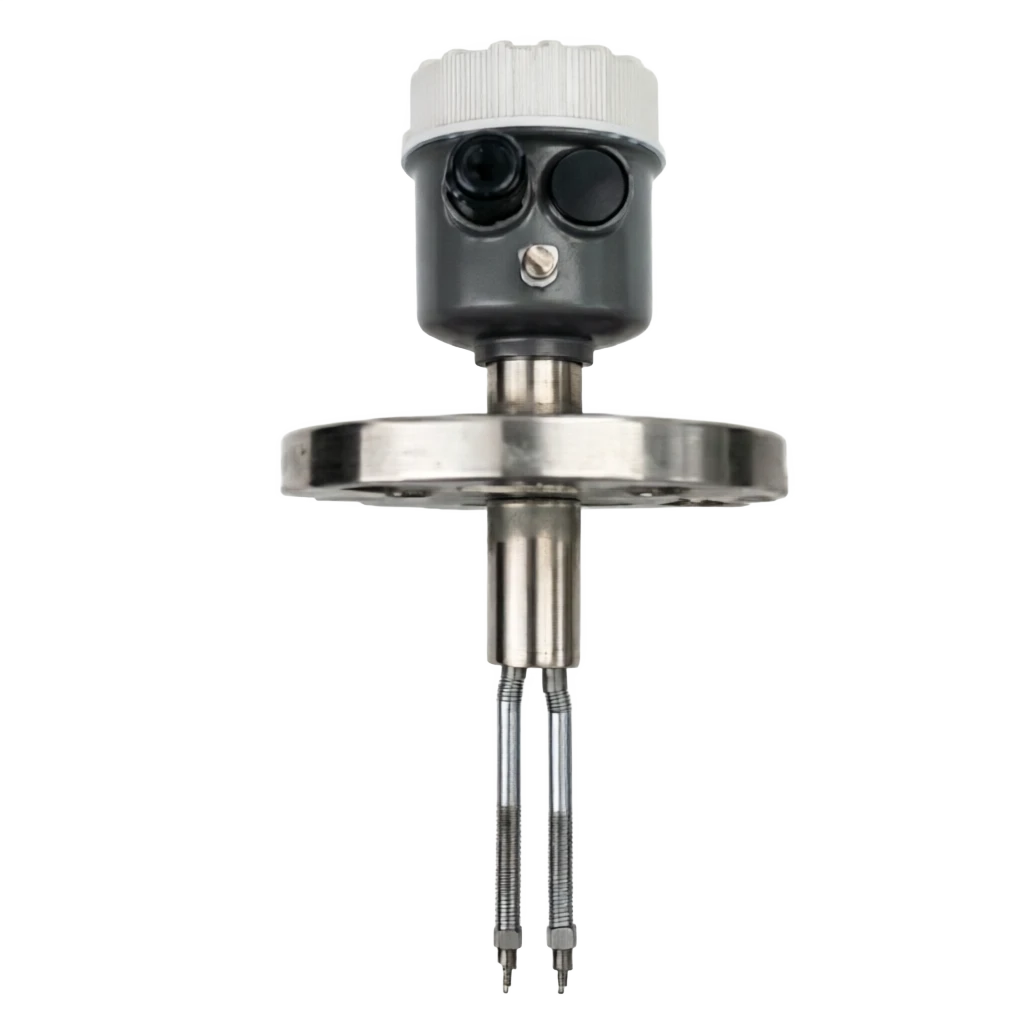
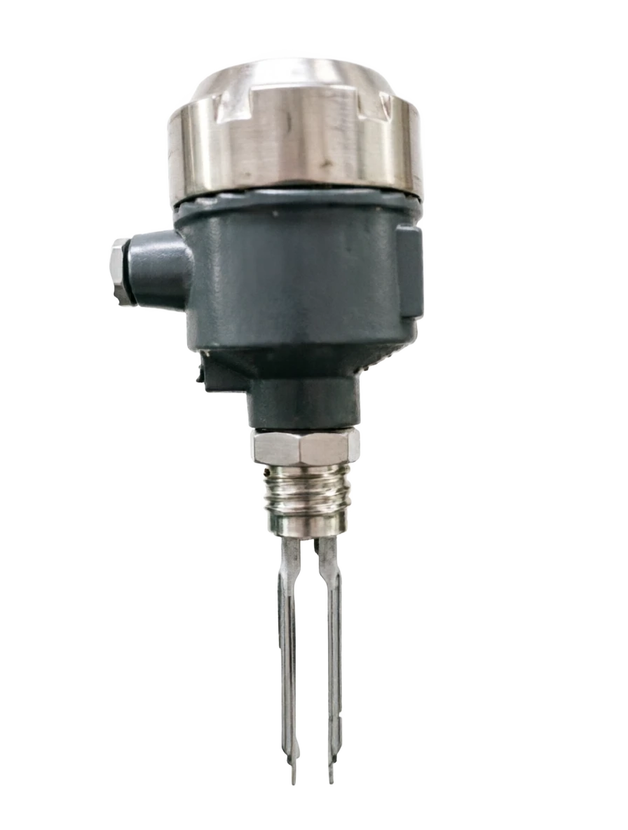
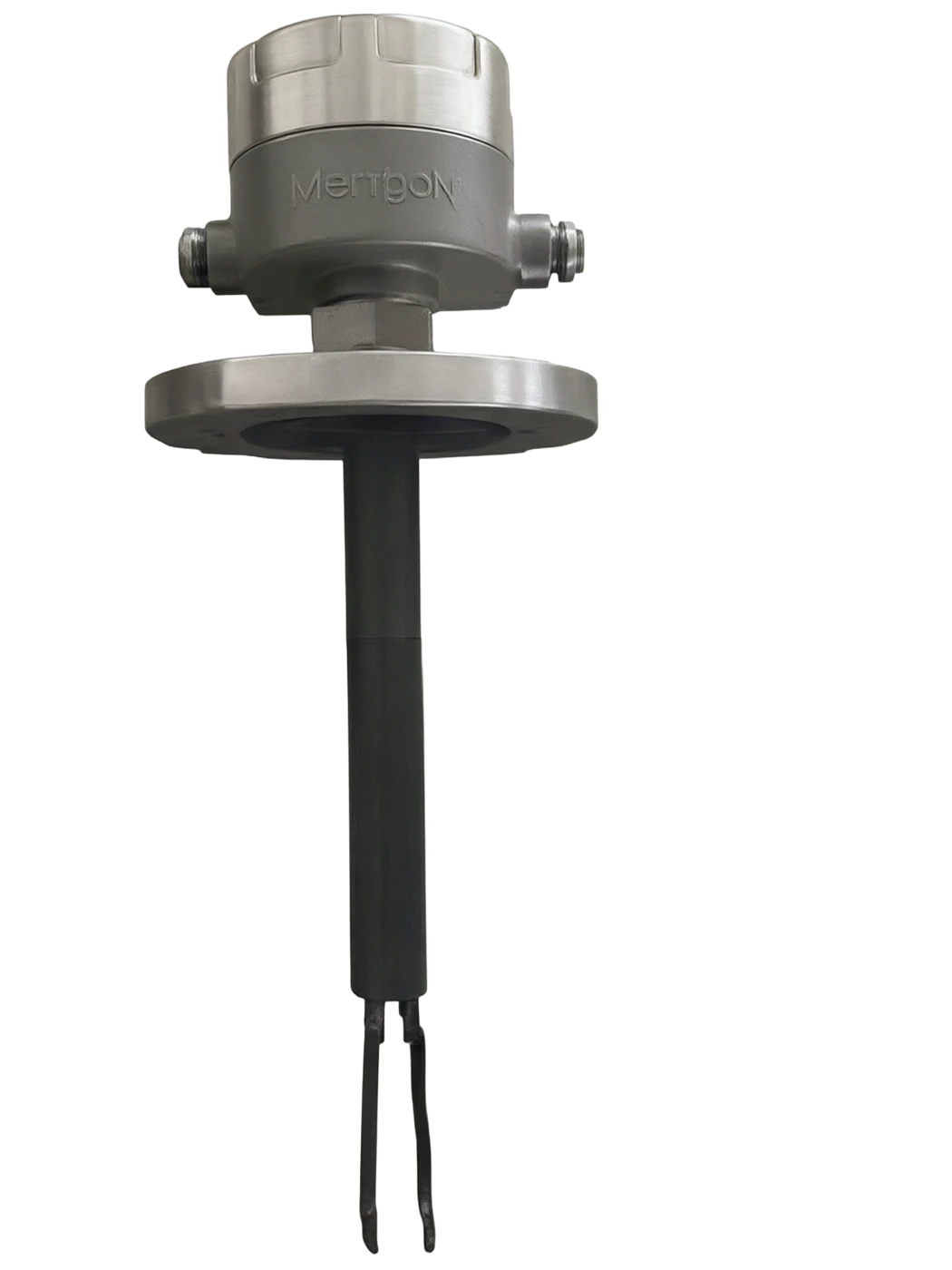
Sound fork-style position controller.

The core is based on the "reverse voltage effect" of voltage ceramics and "proper voltage effect". (b) Two voltage ceramics inside the instrument are attached to the root of the acoustic fork: the voltage ceramics on the incentivized side produce cyclical transformations with the exchange voltage incentive, driving the acoustic fork with an inherent concoction frequency vibration (usually around 200 ~ 1200 Hz); The voltage ceramics on the other side generate a turn charge when the acoustic fork is vibrating and convert mechanical vibrations into telecommunications backsupping circuits. The system forms a closed ring self-repressors. (b) The sound fork is in a steady state of conversation and the oscillation signal is stable in air-borne condition; When the material touches the fork, the vibration of the fork surface is partially absorbed and blocked, with the equivalent of adding mechanical loads to both ends of the acoustic fork, increasing resistance of the oscillation system, decreasing amplitudes and frequency deviations. Internal instrument detection.

  1. 01

    The sensitivity of the acoustic position controller to the different density media varies considerably: liquid, slurry (density g/ cm³) has a significant effect on forklifting and has a high sensitivity; And low-density gas, light powder (density)

  2. 02

    0.5 0.3

  3. 03

    1 & Power Incentive & Incentive Circuit Generation 200 ~ 1200 Hz

  4. 04

    2 · Piezoelectric drive · The drive-side piezoelectric ceramic uses the inverse piezoelectric effect to vibrate the tuning fork.

Sound fork position controller selection support

Provide survey missions, media and installation conditions and obtain product configuration advice.

Contact us
Sound fork position controller . Technical description

TECHNOLOGY & APPLICATION

Understand the principles, the exact selection.

From measurement principles to field applications, the technical features and selection elements of the acoustic fork-type position controller are understood.

01

TECHNICAL GUIDE

Overview

(Tuning Fork Level Contractor / Vibrating Fork LevelSwitch) is a place-detection instrument based on the mechanical resonance principle of voltage ceramic drive, also known as the "Vibration Place Switch".

The core of the instrument consists of two parallel metal vibration forks, which are continuously vibrationd by the inherently tuned frequency (approximately 200 ~ 1200 Hz) by means of voltage elements with electrical incentives; When the material touches the fork, the vibration is obstructed, the amplitude or frequency is significantly altered, the instrument detects the change and triggers the output switch signal to achieve upper- and lower-limit control of the material position or protection of the pump, valve connection.

The greatest feature is that the measurements are not related to the electron parameters of the detected medium (median constant, conductivity), but only to the physical exposure and density of the object, so that there is no problem of failure of the electron-capable bitometer due to the replacement of the medium or the low medium constant.

At the same time, the acoustic forkless mechanical motion components, which are more reliable and have a longer life than float-space switches, have gradually become one of the most widely applied position meters in the field of liquid/slurry/particle material control.

Main features

Developmental progress

The sound tablets originated in the 1960s at Euro-American instrumentation companies, typically represented by Enders+Hauser (Solipant series), VEGA (VEGACAP series), Siemens (SITRANS LVL series), Magnetrol, etc. Since the 1990s, we have been digesting and now have full national capacity and are exporting to countries along the " trail " .

General description · Serial number / Main featuresCross-reference
Serial numberMain featuresBrief description
1Not related to medium electrical parametersBased on mechanical vibration-obstructive neon tests, not influenced by the admixture constant, conductivity rate
2Apply broad mediaLiquids, slurry, particles, light powder can be measured.
3Respond fast.msec response (typical 0.5~2 s)
4It's a tight structure.Forklift is small and can be applied to small packagings, pipes, pumping systems
5UnmarkedSimple debugging after installation is operational without remarking for each medium
6It's a good thing to be in the middle of a jamming situation.Not affected by foam, steam, bubbles, light-weight hangers
7Different modes of outputRelay / PNP/ NPN / Two-line 4-20mA / bus options
02

MEASUREMENT PRINCIPLE

Operating principle

2.1 Pressure and fork-deep

The core is based on the "reverse voltage effect" of voltage ceramics and "proper voltage effect". (b) Two voltage ceramics inside the instrument are attached to the root of the acoustic fork: the voltage ceramics on the incentivized side produce cyclical transformations with the exchange voltage incentive, driving the acoustic fork with an inherent concoction frequency vibration (usually around 200 ~ 1200 Hz); The voltage ceramics on the other side generate a turn charge when the acoustic fork is vibrating and convert mechanical vibrations into telecommunications backsupping circuits. The system forms a closed ring self-repressors.

(b) The sound fork is in a steady state of conversation and the oscillation signal is stable in air-borne condition; When the material touches the fork, the vibration of the fork surface is partially absorbed and blocked, with the equivalent of adding mechanical loads to both ends of the acoustic fork, increasing resistance of the oscillation system, decreasing amplitudes and frequency deviations. Internal circuits for the internal detection of amplitude or frequency changes are identified and trigger switch actions when the threshold is exceeded.

2.2 Testing mechanisms and sensitivity

g/ cm³) has little effect on forklift vibrations, so low-density powder, gas solid, two-way scenes require the choice of "high-sensitivity fork" or "low-density special fork."

2.3 Signal processing and output

The detection circuits pre-enlarge, integrator, A/D sampling and algorithm processing of the acoustic fork, compared to the internal pre-set threshold of "fork block"/freedom. When the signal is detected over the threshold, the corresponding low/high level or drive relay inhalation/release is exported. The instrument usually provides a LED indicator or a LCD display, which is a reminder of the current fork body status.

2.4 Workflow mapping

2.5 Location and location determination of installation

Usually installed on top of the container, side walls or pipes. The location of the installation determines its location alert: the top installation can be controlled as "spill alert" or "upholstery stop"; (b) The perimeter wall is installed as a "ceiling alarm"; (a) The lower side wall is installed as a "lower alarm" or "pump air protection"; Installation above the pump intake also provides "pump clean air protection".

  1. 01

    The acoustic position controllers differ considerably in their sensitivity to the different density media.

    Liquids, slurry (density g/ cm³) have significant forklifting effects and high sensitivity; And low-density gas, light powder (density)

  2. 02

    ≥ <

  3. 03

    0.5 0.3

Motion of work . Step / ActionCross-reference
StepsActionsAnnotations
1Electricity incentivesIncentive circuits generate 200~1200 Hz exchange voltage
2Voltage driveIncentive side-voltage ceramic countervoltage electric drive sound fork
3Sound and fork rupture.The pitchfork stabilizes the vibration with the inherent frequency.
4Vibration feedbackTest side-voltage ceramics for conversion to telecommunications.
5Signal zooming in.Pre-enlarged, intended, A/D conversion
6InterceptionCompared to the threshold, determine if the fork is blocked
7Output ControlRelay / Transistor / 4-20mA / bus output
8Show alarm.LED / LDD indicates the forklift state and alarm
03

PRODUCT STRUCTURE

Product structure

3.1 Complete structure

It consists mainly of the following components:

The header (including display, operating panel, electrical cavity), process connection (snone, flange, cascading, sanitary interface, etc.), vibrating fork (two parallel metal forks), voltage ceramic drive/detection element, signal processing main panel, power supply module, output module.

3.2 Forkware type and selection

3.3 Interconnection and Output Modules

The surface shell

Main functions: Internalised main panels, displays, operating buttons, electrical gas interfaces Typical materials: clasm aluminium / engineering plastic / 316 L SS optional

LED / LCD Display

Main function: Show fork, alert information Typical material: LED indicator / LCD digital tube

Key / Dial

Main function: In situ setting sensitivity, delay, upper and lower limits

Electrical connection

Main function: Power / Output connection Typical mass: M20 / 1/2 "NPT/ Waterproof cable lock

Process connection

Main function: Connect to container / pipe Typical material: screw G1 / G2 / Frank DN50 / Health Level Tri-Clamp

Vibration fork

Main function: Core sensitive element, vibration + blocker detection Typical material: 316 L SS / Hapsy alloy / PTFE coating

Power-pressure ceramics

Main function: Driver + Test for fork vibration Typical material: PZT voltage electro-porcelain

Power module

Main function: Power supply for internal circuits Typical material: wide voltage 24 VDC / 220 VAC

Signal Processing Main Panel

Main function: signal amplification, algorithm processing Typical material: MMU + Simulate frontend

Output Module

Main function: Relay / 4-20mA / bus output

Forktype

Structure module: Structural characteristics Main function: length of fork length Typical material: typical application

Standard Short Fork

Structure module: approximately 50~150 mm length, forklift compact main function: 50~150 mm typical mass: general liquid, upper and lower limit warning of slurry

Extend the fork

Structure module: Longer pole + fork body Main function: 150 ~ 1000 mm Typical material: small packagings, deep tank fluid level alert

Soft cable fork

Structure module: Soft Cable + End fork: 500~4,000 mm for typical materials: large / silo / high-level measurements

Health level fork

Structure module: Forklift, Tri-Clamp Health Level interface, main function: 50~100 mm Typical material: food, beverage, pharmaceutical industry

High viscosity fork

Structure module: forklifts increase spacing, amplification increase, main function: 80~200 mm typical material: highly sticky liquids such as oil, resin, syrup, etc.

Short fork on side

Structure module: Side-loading screw / French structure. Main function: 40~80 mm typical material: side wall installation, upper / lower limit alarm

Relay DPDT

Channels: 1 Channel Typical load capacity: 250 VAC / 5A, 30 VDC / 5A Application scene: upper- and lower-level alert control, pump, valve-linking

PNP / NPN Trilinear

Channels: 1-2 Channels Typical load capacity: maximum 100 ma applications scenario: direct-to-small relay, PLC digital input

A second-line system 4 - 20 mA

Channels: 1 Channel Typical load capacity: 24 VDC round road power, maximum load 600 times

AC Two-line System

Channels: 1 Channel Typical load capacity: 24~240 VAC application scene: direct access to traffic load loops

Field bus

Channels: 1 Channel Typical Load Capacity: Hart / Modbus / IO-Link Application scene: Integration with PLC / DCS / Industrial 4.0 System

04

TECHNICAL GUIDE

Analysis of strengths and weaknesses

4.2 Main shortcomings

4.1 Main advantages

Not related to medium electrical parameters

Note: Not dependent on the adsorption constant, conductivity, magnetic conductivity; applicable to liquids, slurry

Wide range of media application

Note: Water, oil, alkaline, slurry, particles, paste, low viscosity liquids can be measured

Respond fast.

Note: millisecond response (typical 0.5~2 s) suitable for emergency connection control

Tight, small, tight structure.

Note: Fork size small and can be installed in small packagings, pipes, compact space

Free of designation, self-adaptation

Note: Simple debugging is available after installation, and no re-marking is required for media

It's a good thing to be in the middle of a jamming situation.

Note: Not affected by foam, steam, light bubbles; anti-emagnetic interference

Long lifespan, high reliability

Note: No mechanical motion parts, no failure time on average MTBF ≥ 100000 hours

Flexible installation

Description: Multiple installation methods such as top insertion, side fitting, plumbing installation, sanitary grade Tri-Clamp

It's good security.

Note: Low working voltage, essential security; blastproof model used in flammable explosive settings

Price is moderate.

Note: Lower than ultrasound, radar position count prices, higher value for money

Disadvantages and use restrictions

Not applicable for high sticky attachment media

Note: Very sticky asphalt, rubber, waxy coding, failure

Not for Hard Particle

Note: Damage from large hard particles (>20 mm) vulnerable forklift

Not applicable to very low density media

Note: Low density medium (LID) < 0.3 g/ cm³ ) Inadequate fork-blocking, prone to miscalculation

Not for very high temperature / pressure

Note: Special design is required for some high-pressure, high-temperature conditions, and normal models are restricted

Not applicable to large foam media

Note: Heavy foam may be triggered by error; however, general foam conditions are acceptable

Fork is vulnerable.

Note: Forkware detail, transport, installation, and vulnerability to shock damage in operation

No continuous location applicable

Note: A fork-to-fork position switch usually gives only a point-to-point signal and cannot be measured continuously

05

APPLICATIONS

Application area

Its low sensitivity to the electrical properties of the medium, fast response and reliability make it suitable for a wide range of industrial liquids.

Common applications are shown in the table below:

Typical application cases

(1) Watershed Watershed Control: Installation of a pitch-fork-style table switch on the side wall of the water pool as a control signal for the "low-water slot stop pump" and "high-water level pump" to replace the traditional float switch and avoid problems such as card blockage and drift.

(2) Chemical Response Bases/Limitation Warnings

(b) The sound fork level switches on the response ceiling, control the upper limit of the liquid level to prevent spills and control the lower limit to prevent empty rotations; and also relay electrical signals to connect emergency feed / discharge valves.

(3) Food industry CIP Cleaning fluid control

Install a sanitary Tri-Clamp vibrating fork level switch in the clean-in-place (CIP) piping to signal low-level refill and high-level stop in the cleaning solution tank.

(4) Oil field single-well tank fluid alert

Use battery power + second-line voice-fork table switches in remote single-well tank areas as a spill warning signal for the tank, and remote wireless upload control centre.

(5) Air protection of the plant ' s condensed pumps

Installation of a forklift switch above the pump intake to signal "pump clean empty" to prevent the pump from being burned empty.

Chemical / petrochemical

Application scenario: upper and lower limit control of reaction draughts, pump protections Typical media: organic solvents, acid alkaline, catalyst slurry, oil

Water treatment / Environment

Applying scenarios: water pool, water tank, sewage pool fluid control

Food / Beverage

Apply scenario: storage tanks, sugar tanks, raw materials, fluid control

Pharmaceutical/ Biological

Application scenario: feedstock, buffer, purified water tank fluids

Gas / Energy

Application scenario: oil storage tanks, separators tanks, oil field monowell tanks

Paper / Pulp

Application scenes: slurry, white water pool, black liquid slot level

Electricity / Energy

Application scenario: Condensed water tanks, lubricated oil tanks, cooled water tanks

Metal / Steel

Application scenarios: acid wash, electroplating, circulatory pool

Textile / Printed

Application scene: dye tank, stylist fluid level control

Electronic / Semiconductor

Application scenario: chemical tank, ultra-purified water tank fluid level

06

TECHNICAL SPECIFICATIONS

Technical Parameter Table

6.1 General parameters for the whole machine

6.2 Accuracy and reliability parameters

6.8 Application of electrical parameters for media

Table of technical parameters · Parameters / Technical indicatorsCross-reference
ParametersTechnical indicatorsRemarks
Measurement principlePyro-portic drive fork + block-check—
Measure ObjectLiquids, slurry, particles, light powderMedia density ≥ 0.5 g/cm³
Tuning fork lengthShort fork 50 ~ 150 mm / Extension 150 ~ 1000 mm Soft cable 500 ~ 4000 mmBy container depth
Process connectionG1 / G2 screw; DN50 Frank; 1 "~3" NPT; health grade Tri-ClampBy media and packaging
Power supply24 VDC ±10% / 220 VAC ±20% / Two-line 24 VDC Ring RoadAn optional for width input
Work≤ 2 WTypical 0.5~1.5 W
Output MethodRelays DPDT x 1; PNAP / NPN x 1~2; second-line 4-20 ma; HartOptional by Model
Relay capacity250 VAC / 5A,30 VDC / 5ADisable load
Response time≤ 1 s (typical 0.5 s; adjustable 0.5 ~ 30 s)It's set.
Medium density≥ 0.5 g/ cm³ (liquid); ≥ 0.3 g/ cm³ (particle)—
Process medium temperature40 ~ + 150 °C (standard); -40 ~ + 250 °C (high temperature)Slotting by Model
Ambient temperature40 ~ +70 ℃—
Operating pressure0.1 ~ + 4.0 MPa (to process connection specifications)—
Ingress protectionIP65 / IP66 / IP68By Model
Explosion protection markingEx d IIB T4 / Ex d IIC T6 / Ex iIC T6 (by model)—
Housing materialArgument/ Engineering Plastic / 316L SS optional—
Tuning fork material316L SS / Hapsy Alloy / PTFE coating / titaniumPress Media
Display typeLED Double Colour Status Indicator / LCD Digital Drum / LCD Chinese DisplayBy Model
Electrical connectionM20 / 1/2 "NPT/ Waterproof Cable Locker / M12 ConnectorPress the order.
MountingTop/ Side / Tilt / Health Level Tri-Clamp / Pipe InstallPress the scene.
Weight0.5 ~ 5 kg (by fork length)—
Technical parameter table · Parameter / IndicatorCross-reference
ParametersIndicatorsTest Conditions
Repeatability±0.5 mmLaboratory water-purification tests
Response time≤ 0.5 s (default)/ 1 s (modifiable)Standard liquid
Action Delay0.5 ~ 30 s truncableOn site adjust to media
Insulation resistance≥ 100 MΩ500 V mega-eats
Pressure resistance2500 VAC / 1 minPower-to-ground stress.
MTBF≥ 100000 hoursAverage no-facilities time
EMC CompatibilityGB/T 17626 / EN 61326Industrial-level electromagnetic compatibility
Fork lifetime≥ 100000000 secondary vibration cycleContinuous vibrating work
Temperature drift≤ ±1 mm / 10℃Temperature compensation type
Media TypeDensity g/ cm³Typical applicationSensitivity advice
Water, sewage≈ 1.0Water, sewage, acid.Medium / High-level sensitivity
Oil0.7~0.9Crude oil, diesel, cooking oil, lubricantsHe's a smart guy.
Slurpee.> 1.0Catalytic, pulp, starch.Very smart.
Particle material0.5~1.5Coal, sand, plastic particlesHe's a smart guy.
Light powder.< 0.5Flour, milk powder, coal powder (low density)Forkware for special use
High-glue liquid> 1.0asphalt, honey, resinForkware with high viscosity
07

SELECTION GUIDE

Select Table

7.1 Naming rules

Selected examples

TF-T-R-0100-T1-P3-L-D-6 means sound fork, top-load, relay output, fork length 100 mm, temperature 150°C, pressure 4.0 MPa, 316L material, blastproof type, IP66 protection.

7.2 Summary of commonly used models

Selective Table . Code Section / Code ExampleCross-reference
Code segmentExample:What's code for?
TF-TFTunning Fork series code
- TypeT/A/S/WT top/ A side-load / S short fork/ W soft cable
- OutputR / P / N / I / AR Relay / PPNP / NNPN / I 4 - 20 mA / AAC Two-line
- Long fork.0100Four digits, in mm = 100 mm
- TemperatureT1/T3T1 150℃ / T3 250℃
- Pressure.P1/P3P1 1.0 MPa / P3 4.0 MPa
- MaterialsL/H/TL 316L / H Haps Alloy / T titanium
- Bomb protection.N/D/IN / D barlast / I Benan
- Protection5/6/85 IP65 / 6 IP66 / 8 IP68
Selecting Table . Model / Forkbone TypeCross-reference
ModelForktypeOutputTemperature rangePressure rangeApplications
TF-TS-0100Short fork 100mmRelays40~150℃1.0 MPaGeneral fluids are at the bottom of the line.
TF-TP-0100Short fork 100mmPNP40~150℃1.0 MPaPLC Digital Input
TF-AI-0500Side load 500mm4-20mA40~150℃1.0 MPaThe side-packed continuum is being transferred to remote control.
TF-WR-2000Soft cable 2 mRelays40~150℃0.5 MPaSilo, deep tank control.
TF-AR-0080Sidewear 80mmRelays40~250℃4.0 MPaReaction zone, call the police.
TF-TH-1000Short fork 100mmHart40~150℃4.0 MPaThe heat alert.
TF-SH-3000Soft cable 3mHart40~150℃1.0 MPaLarge cans of continuous measurement
TF-AR-PTFESide-Separate PTFE OverwriteRelays40~150℃1.0 MPaStrong acid, strong base tanks
TF-Tri-ClampHealth level Tri-ClampPNP30~140℃1.0 MPaFood, beverages, pharmaceuticals
08

SELECTION GUIDE

Selection Guide

8.1 Basic steps for selection

8.2 Model job recommendations

8.3 Selective care

(1) The length of the fork should be retained in excess

The length of the fork = the alarm position of the container or process point + 30~50 mm excess, avoiding measuring the dead zone.

(2) When the mass density is less than g/ cm³ (e.g., gasoline, light oil), the choice is to use "low-density special fork" and the normal model cannot work in a stable manner.

(3) High viscosity, strong adhesive media (e.g. asphalt, rubber, wax, starch) can easily cause forklift binding failure and it is recommended to be replaced by "radio frequency conductor" or "emitación" position switches.

(4) The blast-proofing scene must confirm the blast-proofing certificate number and grade provided by the manufacturer, and the power supply / output parameters are strictly wired in accordance with blast-proof specifications.

(5) Adequate installation space should be reserved for the site

The vertical space above the top of the flange; length of the fork; leave ≥ 100 mm outside the wall on the side of the container when the top time frame is loaded.

(6) When the temperature of the medium is high above 200°C, the high temperature arctic fork (with dispersive heat structures) is selected to avoid the failure of voltage ceramics.

(7) Care is taken in transport and operation to protect the forklift from shock; it is recommended that the forklift be damaged or replaced immediately after the shape has been transformed, otherwise the alarm may be mistaken.

(8) Cables and power supply sub-chutes should be installed to avoid co-opting with power cables; it is recommended that 24 VDC be used to isolate the power supply.

(9) The health level application should be based on the Tri-Clamp interface, polished 316 L forklift, rough surfaces Ra ≤ 0.8 μm.

(10) For solid particles, crystallized, condensable media, priority is recommended for acoustic fork+heat-accelerator combinations.

8.4 Summary

It is one of the most widely applied point-to-place switches in industrial sites that, with the advantages of insensitivity to the medium electron parameters, responsiveness, high reliability, flexibility in installation, is able to perform the most liquid/slurry/particle upper- and lower-level control tasks. The selection needs to be combined with factors such as medium density, temperature pressure, installation, output, etc., and prioritizes the selection of mature, well-established, applied, and well-established mainstream brands to ensure long-term stability.

Selective guidance · Steps / ConcernsCross-reference
StepsElements of concernCommon Options
1Media TypeLiquid / Slurry / Particle / Light powder / Health-level medium
2Medium density≥ 0.5 g/ cm³ application; < 0.3 g/ cm³ requires a special low density forklift
3Work temperatureCold ≤150℃ / High temperature ≤250℃
4Work stress.Constant / 1 MPa / 4 MPa
5MountingTop/ Side / Tilt / Sanitary / Pipe Install
6Output FormRelay / PNAP / NPN / 4 - 20 mA / Hart / AC two-line system
7Explosive protection requirementsNormal / Detonation / Bennan
8Ingress protectionIP65 / IP66 / IP68
9Tuning fork material316L / Hapsy Alloy / PTFE / titanium
10Tuning fork lengthCalculated by container diameter / installation depth
Typical Work StatusRecommended ModelRationale
Water / Sewage Level ControlTF-TS-0100 / TF-TP-0100The ad hoc electricity constant is irrelevant, water/septics are applicable, prices are affordable
Esmoline / diesel fluid levelTF-AI-0500Side-load continuous measurements, two-line 4-20 MA apogee
Chemical Reaction BaseTF-AR-0080Side-dressing Frank, temperature-resisting 250°C, pressure-resisting 4 MPa
Crude oil / heavy fuel storage tanksTF-WR-2000Soft cable deep into the tank, triggers upper and lower limit control
Food CIP Cleaning LiquidTF-Tri-ClampHealth level Tri-Clamp interface, 3-A / EHEDG
Pharmaceutical purification tanksTF-Tri-Clamp /TF-TS-0100 Photo-paintingHealth grade material, meeting GMP requirements
Air protection of the plant ' s condensed pumpsTF-TS-0100 Side-by-sideSides are mounted above the pump inhaler, millisecond response protection, pump.
Strong acid / strong base tankTF-AR-PTFEPTFE fork-painted, corrosive
Water treatment and medicine tanksTF-TS-0100-PNPPNP output, directly linked to PLC digital input
Oil fields can call the police.TF-WR-2000 Double-line SystemBattery + Second-line 4 - 20 mA Remote Monitor