
PRODUCT TECHNOLOGY
Thermal electrical resistance (thermal voltage) verification simulator
Operating principle
Thermal resistance (thermal voltage) verification of the simulations of the work.
Thermal resistance and the "temperature-electric parameters" correspondence of thermoelectric dolls are defined by international/national scales: Thermal resistance is used IEC60751 ( Pt100 :R(t) = R0 ( 1 + At + Bt²), 0 ℃ Time 100 Ω); The thermoelectric dolls use the IEC 60584-minute table (the Sebek thermodynamic-temperature function). (a) The CVD (Callendar-VanDusen) equation and multiform coefficients for the full-part table of the simulation machines to be accurate in two-way conversion of "temperature resistance/mv": conversion of electrical resistance/mv to temperature at measurement; The output is done by converting the fixed temperature to target resistance/mv and accurately occurring. Conversion error and multiform proposed difference ≤ 0.05 ℃ is usually small
- 01
01 times with a "continuous slope" output capacity (0.1 ~ 99.9 times/min adjustable) to observe the entire-way tracking of monitors. Thermal doll imitates the output of fine mvolt power (resolution 1).
- 02
Thermal resistance measurement uses four-line constant current incentives: instrumentation to export mA (typically) constant current to sensors, to detect direct pressure reduction at sensitive end points and to eliminate the effect of the bar-line electrical resistance; compatible three-line system, two-line (triline system with asymmetric error in the bar). Thermal doll measurement uses high resistance to mvolts.
- 03
1 Parameter setting · Select the fraction / wire-form/ cold-end mode = Cover 8 thermoelectric dolls + 6 thermoelectric resistance = Verify configuration
- 04
2 Connect Access to detected circuits using a four-line system (RTD)/ Compensatory Guide (TC) End-to-end alert. Verify Backway
Structure
Thermal resistance (thermal voltage) verification of the simulations of the structure
Validation of the sequins by the "Signometer Measurement Module" + the "Significance Event Module" + the "Cool-end Compensation Module" + the "Putting" + the typical end-end layout "Input" and "Output" groups: provided by the input group 4 End (RTD 4-line I+/I-/S+/S- or TC+/TC-), provided by the output group 4 End (extraction / mvolt occurrence end). The two sets of enders of the two-channels are fully independent and can be connected externally at the same time. Thermal voltage ends use the equivalent of a temperature block structure integrated with copper rows, cold end sensors are embedded in the centre of the equivalent mass to ensure end-transmitters input; Transponder current output ⁇ (test line) instrument mA measurement end + 24 V power, which forms a complete closed ring.
- 01
Subtemperature is consistent and accurate. The standard connection for checking the transmitter is: a simulation output end
- 02
♪ (compensatory lead) ♪
- 03
1 • Microvolt measurement circuits • Thermal volts volts high-precision measurements . 0.01% RD, resolution 1 μV
- 04
2 • Resisting measuring circuits • Four-line constant currents to stimulate thermal resistance measurement • constant currents 1 mA Four-lined to eliminate wire resistance.
Application area
Thermal resistance (thermal voltage) verification simulator
The complete description shows the technical sections.
- 01
1 . Temperature Carrier Validation . Simulator Signal Validation & Quantification & Quantum . Double Channel One Source + MA Collection
- 02
2 Temperator / Numerical numeric verification · Full-scale distribution point verification and alarm setting · Step / Slipper output
- 03
3 DCS / PLC input card testing • Simulation signal authentication channel accuracy and scale configuration + desktop multiple channel
- 04
4 Recorder and data acquisition system verification = Pyro-consistent simulation / change temperature signal verification record accuracy = slope output and long-term stability
Selection Guide
Thermal resistance (thermal voltage) proofing simulations .
Summary: The thermal electrical resistance (thermal voltage) proofing simulator is the technical core of "Internal Spectrometers" in two-way conversions + Precision Resistance / millivolt measurement and occurrence + Cold End Compensation Three Models + Fault Simulation" and uses telecommunications to repeat temperature to compress the secondary modulation from hourly heating to minutes, along with circuit failure separation and lock validation capabilities. It is not a substitute for the dryer's calibration of the sensor's body, but it forms a "one-time tool chain" with the dryer, the multifunctional process calibration machine. The selection follows the ten-step decision on the "Specific 1: 4 Precision Quantification & Speculation Quantities" approach.
- 01
Economy Single channel survey / source, common fraction number Victory VC14 / Yorid UT620 1000 ~ 3000 CNY Maintenance of class / failure diagnosis
- 02
Standard Type Double channel one source + ma + 24 V ConST 312 / Additel 222 3000 ~ 10000 CNY On-site verification of the main force
- 03
Document Type Task Management + Records + Certificate Fluke 726 / Beamex MC2 10000 ~ 30000 CNY Regular verification certificate
- 04
Power. Document +HART + Multiple Parameters (with Pressure) Fluke 754 / Beamex MC6 30000 ~ 80000 CNY Measuring sector / large enterprises
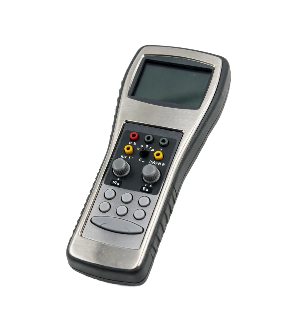
Thermal electrical resistance (thermal voltage) verification spectrometer support
Provide survey missions, media and installation conditions and obtain product configuration advice.
Contact us