ELECTROMAGNETIC FLOWMETER

Electromagnetic flowmeters

MEASUREMENT PRINCIPLE

How do electrodes measure the flow rate?

When the channel fluid flows through the magnetic field, the sensor voltage is generated between the electrodes on both sides. When the magnetic field and the tube is in place, the voltage increases with the average flow speed. The converter calculates volume flow based on current speed and the area of the pipe block.

E = k · B · D · v The sensory power is proportional to the current speed.

For conductive liquids; the selection of the type requires checking the medium conductivity rate, full tube conditions and the location requirements.
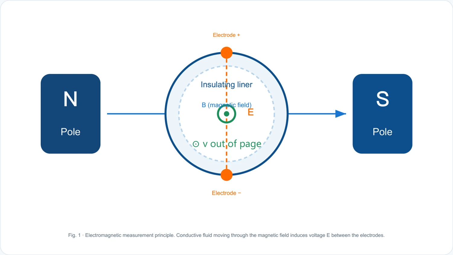
An indication of the relationship between electromagnetic flow counter magnetic field, electrodes and liquid flow speed
Faraday's electromagnetic induction.

Make the selection more relevant to your work.

Tell us to measure the medium, the flow range and the conditions for installation, and get a professional selection.

Contact us
· Technical Note

The following is a technical reference for classification, and the scale and configuration of the specific model is confirmed in conjunction with the work.

TECHNOLOGY & APPLICATION

Understand the principles, the exact selection.

From measurement principles to field applications, the technical characteristics and selection elements of the electromagnetic flowmeter are understood.

01

MEASUREMENT PRINCIPLE

Operating principle

Based on Faraday's electromagnetic laws.

When conductive liquids flow in the magnetic field, the positive and negative ion in the liquid is moved in the opposite direction by the Lorenz force, creating a sensory electric motion between the electrodes vertically in the direction of the magnetic field and the direction of the flow.

The size of the sensor ' s dynamic is proportional to the mean flow speed v, magnetic induction strength B, and measurement tube inner diameter D. Because the tube path is constant with the magnetic field, the electric motion is in a strict linear relationship with the flow speed, and the volume flow can be converted by combining the tube cross-section area.

Measurement formulaClick to see the big picture
E = k B D & v E: Sensor electric motion B: Magnetic induction strength D: Measurement of tube inner diameter v: Average flow speed k: instrument constant
Measurement formulaClick to see the big picture
Q = ( ⁇ D2/4) Q: Volume Flow - Q Q = positive for sensorial electric motion E, output signal linear, open-ended.
Technical IconClick to see the big picture
Electrodes + inner line (insulation) NSB (magnetic field) E Magnetic poles Magnetic poles ⁇ current speed v. (vertical paper facing outward) — figure 1 EMP measurement principle: conductive liquid cutting magnetic lines, generating induction electric motion between two electrodes E

Key premises

The detected medium must be conductive liquids (conductive ≥5 μS/cm). Therefore, it cannot measure gases, vapours, oils, and liquids with too low conductivity, such as ion water, pure water, etc.

02

PRODUCT STRUCTURE

Structure

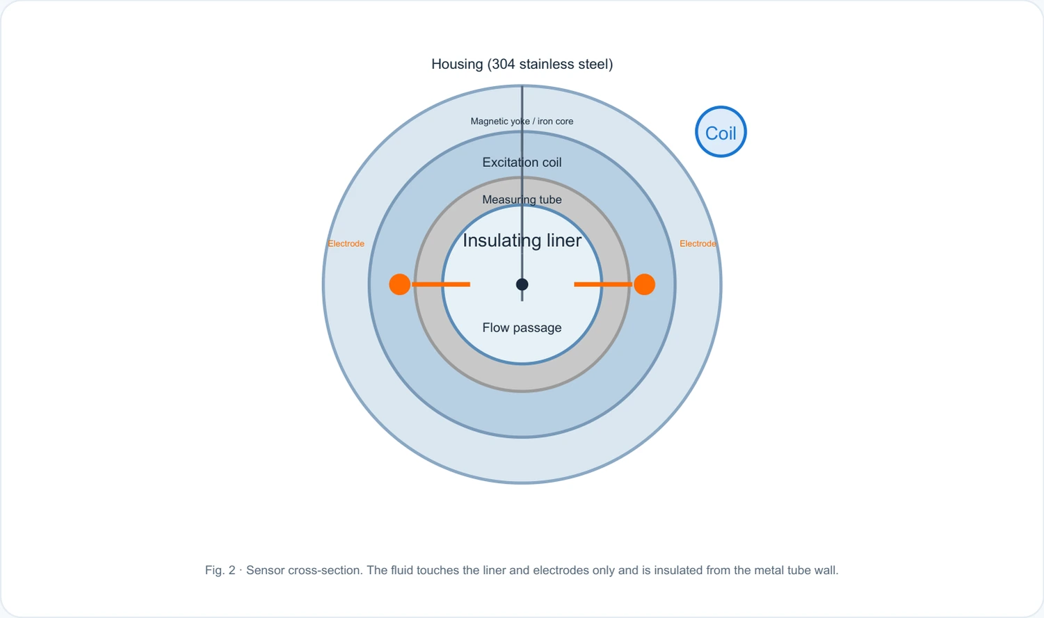
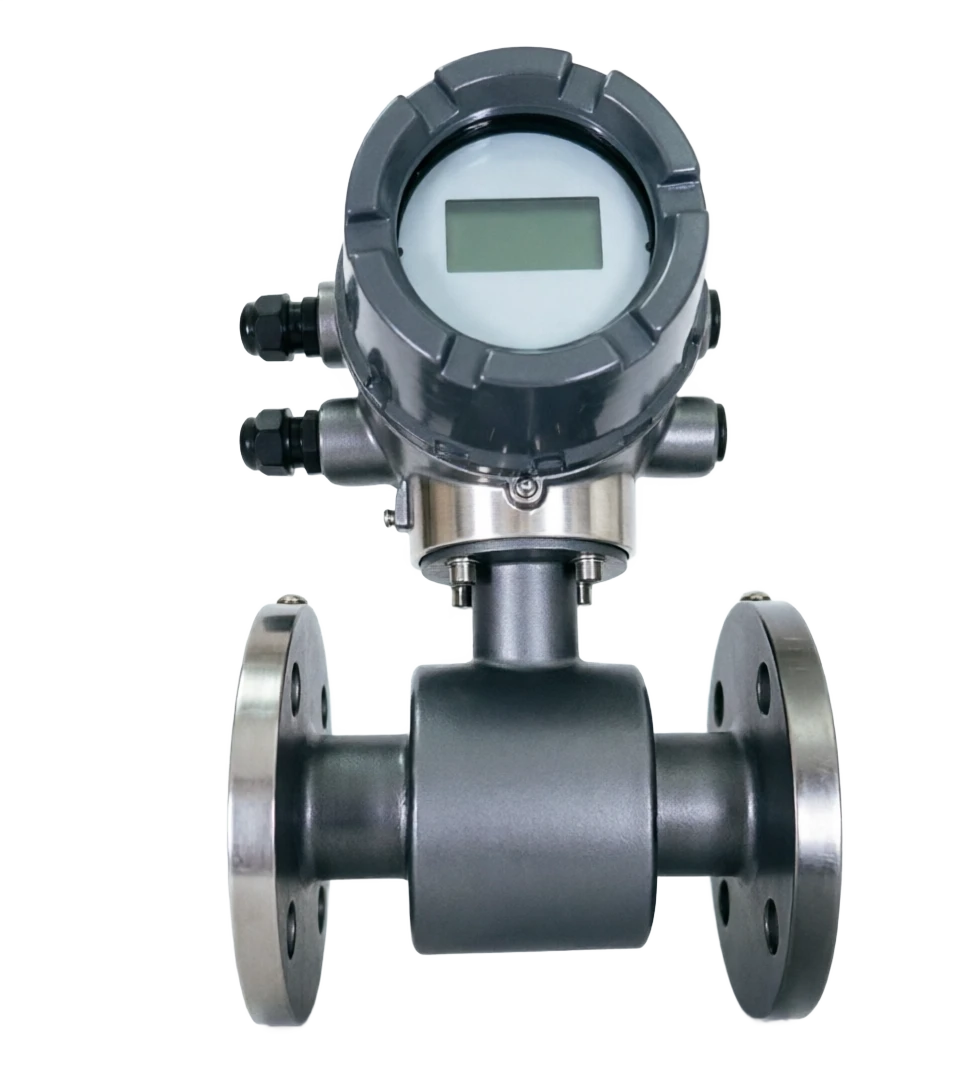
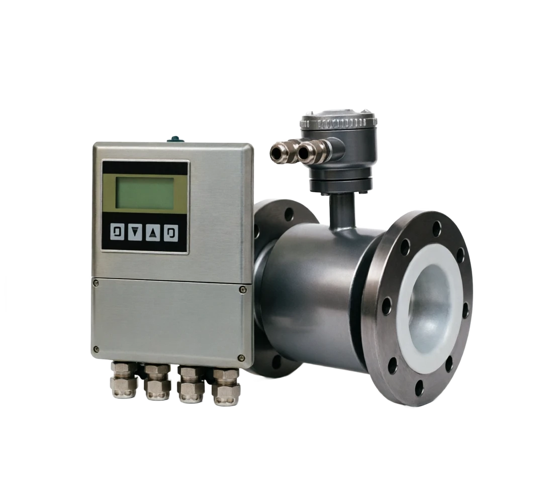
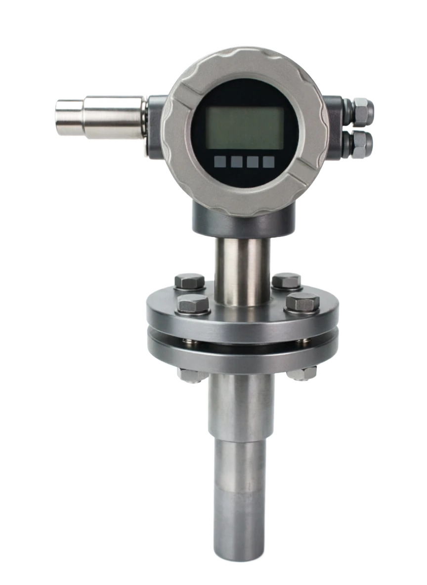
The electromagnetic flowmeter consists of two main modules, sensor (measurement) and converter (sign processing), which can be integrated or installed separately.

Technical IconClick to see the big picture
Crust (304 stainless steel) Magnetic / iron core wires magnetic rims measurement catheters intrapolity (insulation) internal lining (insulation) hydrologic channel Figure 2 Sensor routing profile: fluid only contact "inline + electrode" insulates the metal pipe wall

Sensor

Survey catheter

Usually for stainless steel, it provides rigid fluids.

Inline

Insulation layer, to prevent signal short circuits (rubber / PTFE / PU, etc.)

Ethylene.

Exposure to liquids, induction of electric motion (316L / Ti / Ta / Haq alloy)

Magnetic Circle + Magnetic Spectrum

Create stable metallagnetic fields.

Shell + Frank

Protection and pipe connection

Converter (Convert)

Pre-Zoom In

Magnify weak sensor electric motion (mv)

Model conversion

Digitize the analogue.

Microprocessor

Magnetic control, signal calculator, compensation and accumulation

Display

LCD shows instant flow / cumulative flow / flow speed

Output Interface

4-20mA / Pulse / RS485(Modbus) / HART

03

TECHNICAL GUIDE

Advantages and disadvantages

Advantages

No moving parts, no stopping flow elements

No moving parts, no resistance elements, small pressure loss.

Two-way measurements

The range is wide and the flow is measured in both directions.

Medium Parameters Low Impact

The results are not influenced by temperature, pressure, viscosity, density.

Linear Output

Output and flow linearity, high precision (up to ±0.5%).

Come on, come on.

No mechanical inertia, suitable for instantaneous flow and aggregate measurement.

Percussion, wear and tear

Inlines and electrodes can be customised to media.

Low maintenance

Almost unmaintained, long-lived and long-term stability.

Disadvantages / Limitations

Media Limit

Only conductive liquids are measured, and gas, steam, oil cannot be measured.

Lower Electrotransaction Rate

There is a lower limit for electrical conductivity (≥ 5 μS/cm).

Temperature limit

The temperature of the medium is limited by internal liners and coils and it is not appropriate to measure the high temperature medium.

EMPLOYMENT

It is vulnerable to external electromagnetic interference and requires good grounding.

High installation requirements

A full tube, sufficient direct sections to avoid bubble and solid deposition.

Large caliber cost

The price of large calibres is relatively high.

04

APPLICATIONS

Application area

Municipal water supply

Water supply, water purification plant flow monitoring and trade measurement

Chemical industry

Algebra, corrosive media, process control

Petroleum chemicals

Final oil, additives, blast-proof area measurements

Sewage treatment

Sewage, wastewater, backwater flow measurement

Food and drink

Measurement of liquid flow in compliance with hygiene requirements

Metallurgy and electricity

Refrigeration, recycling, saline water measurement

Agricultural irrigation

Water pipeline, irrigation area flow measurement

Industrial processes

Process control, energy consumption accounting, DCS integration

05

TECHNICAL SPECIFICATIONS

Technical Parameter Table

  1. 01

    Flow range reference table (caliber ⁇ flow)

The flow is between the "lowest ~ maximum" and the detectable range at the same calibre, and the selection ensures that normal work flow falls on the upper part of the zone.

DN150DN900

  1. 01

    66

  2. 02

    17

  3. 03

    90

  4. 04

    37

Technical parameter table · Parameter item / IndicatorCross-reference
Parameter ItemIndicatorsParameter ItemIndicators
Measured mediumPower-transmitting liquidsConnectionFranc connection (GB/T)
Nominal pressure0.25 / 0.6 / 1.0 / 1.6 MPaIngress protectionIP65 / IP67 / IP68
Process medium temperature≤ 120 ℃ (Embo-Og)Output signal4-20mA / Pulse / RS485 / HART
Environmental humidity5% ~ 95% RHElectrode material316L / Ti / Ta / Haq alloy
Table of technical parameters Cal. (mm) / Minimum flow (m³/h)Cross-reference
cal. (mm)Minimum Flow (m³/h)Maximum traffic (m³/h)cal. (mm)Minimum Flow (m³/h)Maximum traffic (m³/h)
DN200.3211.30DN25052.291767.60
DN320.8028.94DN350102.343463.32
DN501.9670.69DN450169.215728.28
DN805.01180.86DN600300.4510164.74
DN12512.27441.94DN800534.0618095.71
06

SELECTION GUIDE

Selection Guide

  1. 01

    Five-step selection.

  2. 02

    The fixed caliber drops in the upper part of the zone by normal flow.

  3. 03

    Select the inner liner by medium corrosiveness + temperature select the inner liner

  4. 04

    Optimum electrodes select electrodes by the corrosive medium

  5. 05

    Fixed and export power 220 V/24 V, output 4-20mA/RS485 etc.

  6. 06

    Set installation form one / split + protection level

  7. 07

    Table of internal liner mass selection

The internal lining is the only insulation that is in contact with a large area of the medium and is selected by a combination of "Mediatype + temperature".

  1. 01

    Table of electrodes selected

The electrodes are exposed directly to the medium and are resistant to corrosive and electrochemical erosion of the counterpart medium.

Zirconium alloys high end, high reliability oxidation medium

  1. 01

    The installation form selection table is slightly less costly (to connect to cable)

  2. 02

    3 ~ 10 m/s, which ensures accuracy while avoiding long-term hyperactivity.

  1. 01

    Selecting Hints

    When calibration is determined, it is recommended that

  2. 02

    Normal traffic falls between 30% and 90% of the detectable range of the corresponding caliber, and the flow is controlled.

Selection guidance · Inline material / Application mediumCross-reference
Inline massSuitable mediaTemperature rangeCharacteristics
PUR PUR PUSolid particulate plasma, ore, mud≤ 80 ℃It's very vindictive. It's a good brush.
Polyperfluoroethylene F46Strong Corrosion Media40 ~ 180 ℃It's more warm and it's more processed.
Selective guidance · electrodes mass / appliance mediumCross-reference
Electrode materialSuitable mediaCharacteristics
Titanium TiSeawater, salts, chlorinated, sodium hypochlorateCongestion resistant to chlorine ions
HB / HCOxygen, sulphuric acid, hydrochloric acidStrongly Oxidizing Media
Selective Guide · Contrast / OneCross-reference
ComparativeIntegralRemote
InstallClose. Small space.Sensor site, converter remote wall.
Read MethodDirect readings on siteRemote concentration readings
07

TECHNICAL GUIDE

Installation requirements

The accuracy of the measurements is highly dependent on the quality of the installation. Inadequate installation (e.g., pipeline dissatisfied, inadequate direct section, poor landing) leads to reading drifts or even impossible to measure.

Technical IconClick to see the big picture
Curved / Valves, etc.
Upstream direct tube ≥ 5 D downstream direct tube ≥ 2 ~ 3 D
Flow meter
DN
Flows to the poach
Note: Upstream, if there are disturbance elements such as bends, valves, the direct section should be extended to ≥ 10 D
Figure 3 Direct pipe installation requirements: ensure sufficient direct tube segment to avoid disturbance flow impact measurement accuracy
  1. 01

    Installation Points

  2. 02

    Full running.

    The sensor must always be filled with liquids, avoiding half-pipes / air pipes

  3. 03

    Straight-barring segment

    Upstream ≥ 5 D (with disturbance ≥ 10 D), downstream ≥ 2 ~ 3 D

  4. 04

    Vertical Install

    Liquids flow from bottom to bottom, and they can be naturally full.

  5. 05

    Ethertic position

    The electrodes should be on the horizontal axis at the time of horizontal installation, avoiding bubble / deposition cover

  6. 06

    Reliable location.

    Pyrotechnics, transducers, pipes, etc., to prevent electromagnetic interference

  7. 07

    Stay away from the jamming source.

    Avoiding powerful electromagnetic devices such as large electrics, transients, welders

  8. 08

    Installation of a no-to-exposure to be installed at high points (gas-removable accumulation), low points (sediment accumulation) not to be installed near the main downstream of disturbance elements such as pumps, valves, etc., to prevent negative pressure, vacuum or visible bubbles from being installed in the pipes from operating without a proper or poorly connected environment without a long-term sensor to withstand a strong vibration or mechanical stress

08

TECHNICAL GUIDE

Maintenance and common failures

  1. 01

    Regular cleaning of electrodes at daily maintenance points

EOD contamination can cause signal drift and regular cleaning of the medium.

Check the internal lining for broken, bubbled, defunct and timely replacement.

Check the site to confirm the good lined up and the endpoint is not loose/corrosive/water in.

Periodic calibrations are recommended to be verified annually to ensure long-term measurement accuracy.

Checking for magnetic and electrical power confirmed that the current and voltage of the electric power are stable within the rated range.

Protection checks check seals, cables, Glen heads to prevent tidal intrusion.

  1. 01

    Common malfunction checklist

Maintenance and common failures · Fault phenomena / Possible causesCross-reference
Fault phenomenaPossible causeQuery
Zero driftEOD pollution, external electromagnetic interference.Check the ground and shield, clean the electrodes.
Small measureElectrodes are down, liner breaks, disgruntled tubes.Check the lining and the electrodes, check the full tube.
Reads are unstable, jumps.Bad ground, interference with signal lines.Regulate the location, and the signal lines are installed.