PRODUCT TECHNOLOGY

Liquid-bit transducer

Operating principle

Liquid-level transducer.

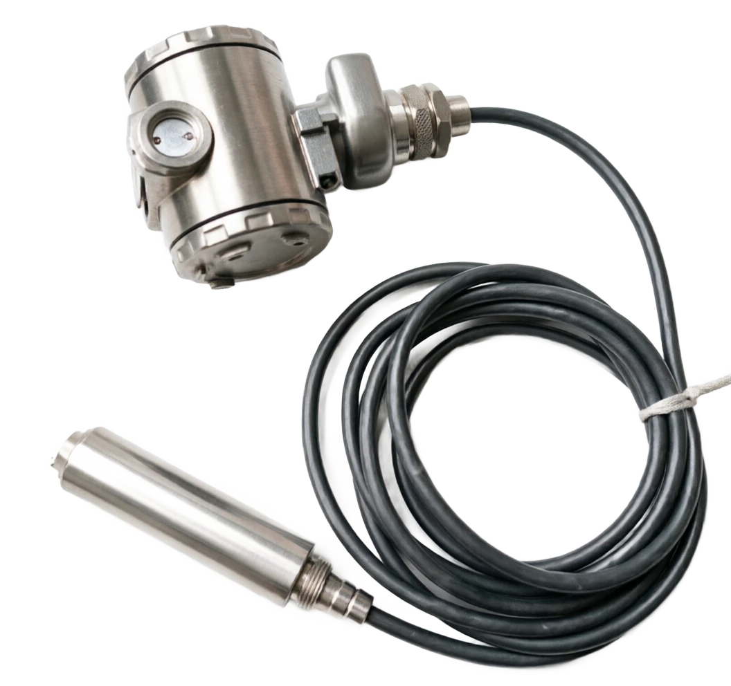
Injecting liquid-level transporters measure liquid levels using static pressure: pressure sensitive elements with stainless steel separators are fed into the bottom of the liquid, and the perceived liquid static pressure P is proportional to liquid-level H: P = old g H (old as mass density, g for gravity acceleration) I = 4 + 16 x (H - H_min)/ (H_max - H_min) (4~20 mA output current I and H linear) / Lever Transmitter, p. 3 Technical summary technical document, liquid-place transductor/Line manual, p. 4 Technical summary document, optional manual manual, manual

  1. 01

    1 Quiet pressure perception Q.O.P. Q.P.

  2. 02

    2 Silicon oil transfer ; Separatic fluids that transmit pressure to pressure-resistant sensitive elements .

  3. 03

    3 Pressure / Capability Sensitive / Bridge Road Resistance Change / Bridge Unbalanced Power

  4. 04

    4 . Signal reconciliation . Magnify + Temperature Compensation + Linearization .

Support for liquid-bit transmitter selection

Provide survey missions, media and installation conditions and obtain product configuration advice.

Contact us
Liquefied-level transducer . Technical note

TECHNOLOGY & APPLICATION

Understand the principles, the exact selection.

From measurement principles to field applications, the technical characteristics and selection elements of LTPs are understood.

01

TECHNICAL GUIDE

Overview

(Live Transmitter) is a liquid-level instrument for the output of continuous simulations or digital signals for real-time measurement of the liquid-level height in containers such as tanks, reaction plumes, ponds and so forth, and uploads the results to the DCS/PLC/SCADA system with industrial standard signals (4-20 MA / FF / Profibus PA / Modbus). Three liquid-bit meters are also called with liquid-level meters (indicator) and liquid-level switches (alert).

This summary summarizes the most common input static fluid transporters (representative products) at the focus industrial site and provides a large comparison table of the technical routes of various liquid-level transporters (static voltage, capacitation, ultrasound, radar, magnetic stretching, etc.) to facilitate horizontal comparison in the engineering selection.

02

MEASUREMENT PRINCIPLE

Modus operandi (large categories and formulae)

2.1 Input static fluids (mainline)

Input fluids measure liquid levels using static pressure

The pressure sensitive elements with stainless steel separators are put into the bottom of the liquid, sensed.

Liquid static pressure P to liquid level H positive ratio: P = old g H (old medium density, g gravity acceleration)

H = P / (old g) (soft density is known to be enough to achieve liquid height)

I = 4 + 16 x (H - H_min)/ (H_max - H_min) (4~20 maA output current I and H linear)

2.2 Signal transmission path (8 steps)

/LiveTransmitter, p. 3 Technical Summary Technical Document . LTP Manual / Lever Transporter, p. 4 Technical Summary Technical Document .

Modus operandi (large categories and formulae) . Serial number / chainCross-reference
Serial numberLinkCritical handling
1Silent Pressure PerceptionInjecting detection, dissociated film pressure.
2Silicon oil transfer.The quarantine fluids transmit pressure to pressure-retarded sensitive elements
3Pressure/ Capability Sensitive♪ Bridges are changing, bridges are ♪ ♪ uneven ♪
4Signal reconciliationZoom in + Temperature Compensation + Linear
5ADC SampleConvert to Number
6CPU CalculatorBy density old conversion fluid H = P/(g)
7D/A OutputConvert to 4~20 MA current
8Digital communicationssupersede HART signal / Modbus / FF
TypeMeasurement principleOutputTypical precisionApply
Input static pressureBottom P = old gH4~20 mA±0.25%FSWells, open wells.
- It's a mono-French silence.P = old gH4~20 mA±0.1%FS- The pressure cans, the response pads.
Modular (large categories and formulae) · Type / Measurement principleCross-reference
TypeMeasurement principleOutputTypical precisionApply
Double French pressureΔP = ρgH4~20 mA±0.075%FSHigh pressure tanks, closed containers
Capacitive⁇ R Change C4~20 mA±0.5%FSPower-transmission liquids, oil and water interfaces
UltrasoundD = c·t/24~20 mA±0.25%FSSewage, canals, canteens.
RadarD = c.t/2 electromagnetic waves4~20 mA±1 mmStrong work, trade measurement
- Convey radar.TDR time-scale reflection4~20 mA±1 mmLow, low, high, high.
MagnetostrictiveTurning wave time4~20 mA±0.5 mmLNG, high precision
Radio-frequency conductor- Stop change.4~20 mA±0.5%FSPowder, particle bits.
03

PRODUCT STRUCTURE

Product structure

3.1 List of main components (10 large components, mainly input)

3.3 Typical input-level liquid-transmitters structure (text description)

Tank mounting fixture → vented cable with atmospheric reference tube → IP68 junction box → stainless steel stem (length equals measuring range) → probe with diaphragm and sensing element. The assembly is immersed in the liquid. The probe senses hydrostatic pressure. The capillary in the vented cable compensates for changes in atmospheric pressure in real time.

/LevelTransmitter, p. 5 Technical summary technical document — Handbook of Options

Top of the probe.

Main function: Waterproof seal + Cable introduces common mass: 316L / Aluminium alloy + IP68

stainless steel pipe / cable

Main function: Support + signal cable circuits Common material: 316 L / polyurethane protective cable

Shell / Seal cavity

Main function: Protection of circuits, tideproofness, common IP68 materials: 316L + O Circle FKM

Isolation diaphragm

Main function: Exposure to media, transfer of pressure Usage material: 316L / Hapsy Alloy C-276/Turn/PTFE

Separatist fluid (silicate oil)

Main function: no gap transfer pressure Usual materials: silicon oil / fluorine

Sensitive components (pressure/ capacitation)

Main function: Pressure ⁇ Telecommunications conversion Usage: single crystal silicon / ceramic capacitor

Signals adjust circuits

Main function: amplification, compensation, linearization Common material: ASIC + temperature compensation

MCU / DSP

Main function: Signal processing + Communication protocol Usual material: ARM Cortex-M

Mine/ Wave

Main function: Mine-proofing, voltage protection

Ventilating cables / hairy tube

Main function: Atmospheric pressure reference (required for input) Common material: polyurethane + gas-transmitting steel

Mounting

Name of component: Application of scenes Main function: Typical instrumentation Usual material: Characteristics

Input (scuba)

Name of component: open pool, deep well, reservoirs. Primary function: Input static pressure. Common material: simple structure, non-destructive tank.

Top French

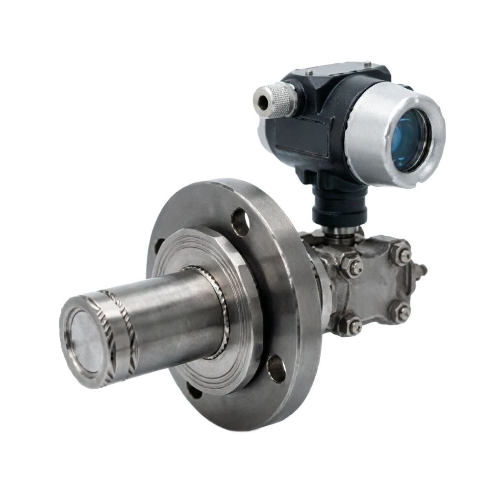
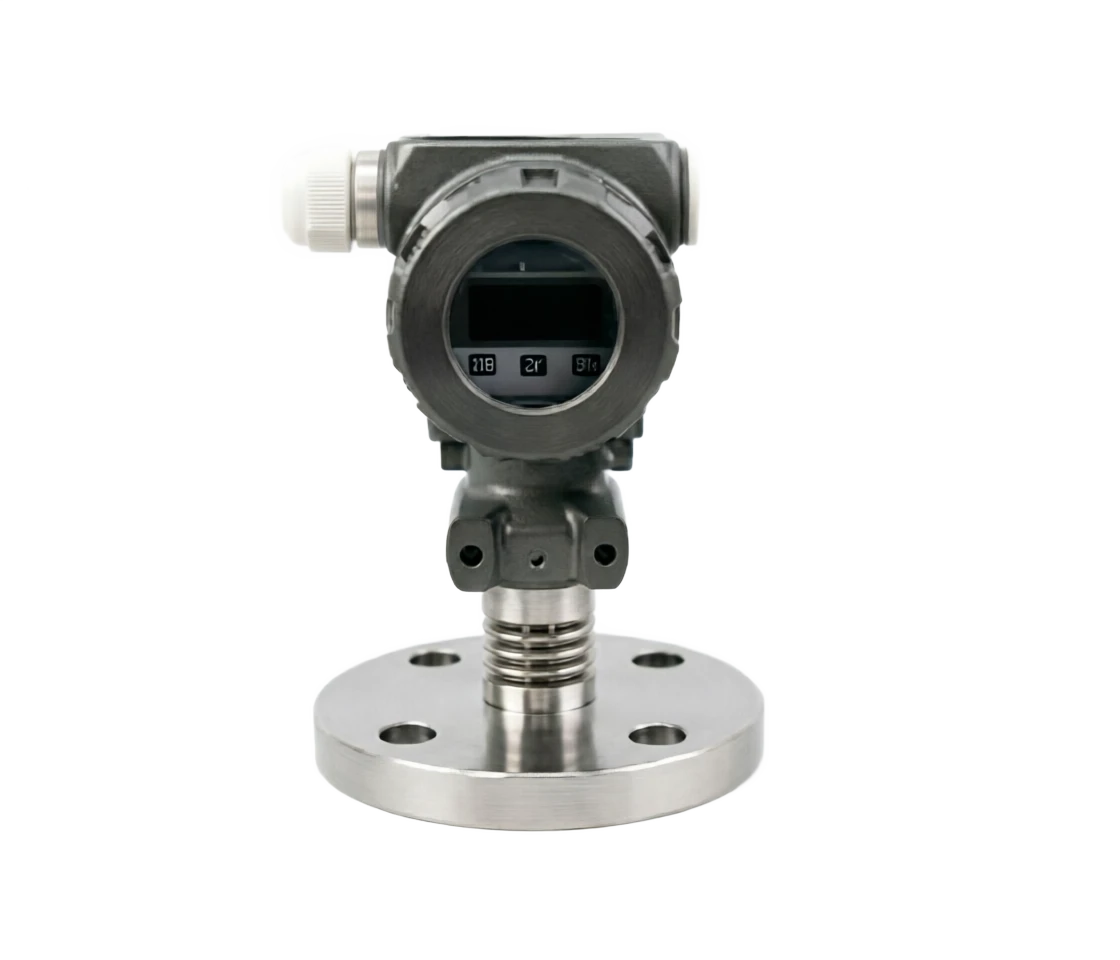
Name of component: constant pressure tank, reaction sheet, main function: mono-French diaphragm, common materials: installation maintenance convenience

Side-load differential

Component name: Cable high pressure tank. Primary function: Double French differential pressure. Common material: long-distance hair piping tube.

Wall-posting

Name of component: plastic, strong corrosive, main function: external supersonic/radar

Side-Standing Bar

Name of component: Small and Medium packagings Main function: Radio frequency conductor / Capable

Transistor

Component name: Strong current, low ⁇ r medium Primary function: Guided wave radar Common material: electromagnetic wave spreading inside the tube

04

TECHNICAL GUIDE

Analysis of strengths and weaknesses

4.1 Main advantages (inputs)

/LevelTransmitter, p. 6 Technical summary technical document — Handbook of Options

4.1 Main advantages (inputs)

Simple structure

Note: No mechanical motion items, high reliability

Price economy

Note: Input cost is only 1/5 ~1/10 for radar

Installation convenience

Note: The liquid is ready to work, the tank is open.

Measurement of stability

Note: Not affected by foam, steam (silent pressure)

Deductible sewage / slurry

Note: Direct contact with membranes, application of dirty stain media

Long-term stability is good.

Note: Ceramic capacitor / single-crystal silic sensitive element 5 years stable

Support for multiple communications

Note: HART / FF / PA / Modbus General Protocol

Densible compensation

Note: Re-intensify the liquid level by setting density

But it's a remote surveillance.

Note: 4~20 MA signal transmission long distance no decay

Disadvantages and use restrictions

Need known media density, old man.

Response: Set old or density rate

Temperature influence film / Silicon oil

Response: Temperature compensation + temperature-specific

Spectrums need to be regularly cleaned (water scenes)

Response: selected from a washing or increased film

Air cables are blocked / tideed

Response: use of drying agents, periodic inspections

Not applicable to corrosive medium

Response: PTFE / Hapsy Alloy / tantalum film

Could not measure interface

Response: differential pressure or magnetic stretch

Limited range (input ≤200 m)

Response: Radar or magnetic stretching selected

Magnificent media membrane impact accuracy

Response: chosen from clean film or non-contact

05

APPLICATIONS

Application area

/LevelTransmitter, p. 7 Technical summary technical document — Handbook of Options

Water / Water

Typical applications: deep wells, reservoirs, clean reservoirs, canals

Oil / Gas

Typical applications: crude oil tanks, finished oil tanks, boreholes

Chemical / Chemical plant

Typical applications: Reaction plume, acid-alkali tanks Recommended instrument type: mono-Franc/Little Radar

Food / Pharmaceuticals

Typical application: CIP, fermentation, syrup tank Recommended instrument type: sanitary mono-Franc/ radar

Electricity / Energy

Typical applications: Condensation, Resupply, Ashbank Recommended instrument type: Single/Bi-Franc/ Radar

Metal / Steel

Typical applications: high-bore feed, tar tank, acid sluice, recommended instrument type: radar / radio frequency conductor

Water treatment / sewage

Typical applications: sewage wells, sludge ponds, regulating ponds Recommended instrument type: input / ultrasound

Paper / Chemical

Typical applications: black, green, pulp ponds Recommended instrument type: radar / ultrasound

LNG / Low Temperature

Typical applications: LNG tanks, LNA tanks

Solid powder / granular silo

Typical applications: cement powder storage, fertilizer silos, plastic particles

06

TECHNICAL SPECIFICATIONS

Technical Parameter Table

/LevelTransmitter, p. 8 Technical summary technical document — Handbook of Options

Technical Parameter Table · Parameter Category / Parameter NameCross-reference
Parameter CategoryParameter NameTypical specification
Measuring PerformanceMeasurement range0~0.5 m input / 0~30 m cable / 0~150 m radar
Measuring PerformanceAccuracy class±0.05%FS / ±0.1%FS / ±0.25%FS / ±0.5%FS
Measuring PerformanceRepeatability±0.05%FS / ±0.1%FS
Measuring PerformanceLong-term stability± 0.1% FS / year (single silicular) / ± 0.2% FS / year
Measuring PerformanceResponse time≤ 100 ms (input) / ≤ 1 s (radar)
Process conditionsProcess medium temperature40 ~ +85 °C (input)/ +200 °C (with dispersible heat)
Process conditionsProcess pressure1 ~ +4 MPa (input)/40 MPa (bi-French high pressure)
Process conditionsMedium density0.5 ~ 5000 kg/ m³ (compensable to be awarded)
Electrical specificationsElectricity voltage16~36 V DC (two-line) / 24 V DC ± 10% (four-line)
Electrical specificationsOutput signal4~20 mA + HART 7 / FF H1 / Profibus PA / Modbus
Electrical specificationsLoad resistance≤ 600 (HaRT)/ 250 (Ben)
Electrical specificationsWork≤ 0.8 W (two lines) / 3 ~ 5 W (four lines)
StructurePostomas316L / Hapsy Alloy C-276/ tantalum / PTFE coating
StructureBody material316L / Aluminium alloy / Cast steel
StructureProcess connectionInput not required / Frank DN50~DN100 / screw G2
StructureShell protectionIP66/IP67/IP68 (Input IP68 required)
Fireproof.Explosion protection markingEx d IIC T6 Ga / Ex ia IIC T6 Ga
Fireproof.Bomb protection certificationNEPSI / ATEX / IECEx / FM
AuthenticationCommunications agreementsHART 7 / FF / Profibus PA / Wireless HART
EnvironmentAmbient temperature40 ~ +80 ℃
EnvironmentRelative Humidity0~100% RH (cooled condensation)
07

SELECTION GUIDE

Select Table

7.1 Type by measurement principle

/LiveTransmitter, p. 9 Technical Summary Technical Document . LTP Manual / Lever Transmitter, p. 10 Technical Summary Technical Document .

Selecting Table . Code / Instrument TypeCross-reference
CodeInstrument typeSuitable mediaTypical precisionPrice slot
LT-HInput static pressureWater, sewage, oil±0.25%FSLow
LT-S- It's a mono-French silence.Constant pressure tanks, acidic acid±0.1%FSMedium
LT-DDouble French pressureHigh pressure tanks, closed containers±0.075%FSMedium High
LT-CCapacitivePower-transmission liquids, oil and water interfaces±0.5%FSMedium
LT-UUltrasoundSewage, canals, canteens.±0.25%FSMedium
LT-RRadarCoercion, trade measurement±1 mmHigh
LT-G- Convey radar.Low, low, high, high.±1 mmHigh
LT-MMagnetostrictiveLNG, high precision±0.5 mmHighest
LT-RFRadio-frequency conductorPowder, particle bits.±0.5%FSMedium High
CodeRangeType of recommendationTypical applications
LR-10 ~ 0.5 mInput / UltrasoundSmall packagings, canals
LR-20 ~ 5 mInput / Mono-FrancProcess tanks, storage tanks
LR-30 ~ 10 mSingle/bi-Franc/ RadarMedium tank
LR-40 ~ 30 mConvey radar / radarDeep wells, large cans
LR-50 ~ 100 mRadar (telemetry)Overdeep wells, reservoirs.
LR-60 ~ 150 m80 GHz radarSpecial Over-Specific
CodeApplicationsType of recommendationRecommended frequency / massRemarks
SC-01Deep well / wellInput + Air cables316L filmEconomy, ease of assembly
SC-02Clearing pool / Sewage poolInput / Ultrasound316L + PTFEQUITE≤10 m
SC-03Constantly pressurized chemical storage tanks- It's a mono-French silence.HastelloyAlgebra
SC-04Sealed high pressure canisterDouble French pressure316L + Filled with Silicon oilHigh-low-pressure side match
SC-05Crude oil / heavy oil tankSingle/bi-Francile + Radar Option316L + HaePay attention to density compensation.
SC-06Reaction to the temperature.Mono-Franc-Gymmetric316L + heat segment≤200 ℃
SC-07Liquefied Gas / Low ⁇ r Medium- Convey radar.Coaxial tubeConvey radar power
Selecting table . Code / Apply sceneCross-reference
CodeApplicationsType of recommendationRecommended frequency / massRemarks
SC-08Bed alkalin tanks for strong corrosionPTFE Mono-Franc/ Convey radarPTFE filmAll PTFE Preservatives
SC-09Oil–water interfaceDouble French pressure316LInterface density difference ≥ 0.1
SC-10LNG / Low Temperature TankMagnetic scalding / Radar cryogenicFor the cold.196 °C applies
Media FeaturesType of recommendationKey reasons
Clear Water / Low StickyInput / Silent PressureEconomy, ease of assembly, stability
CoercionPTFE film / transport radarPreventing metal erosion
Strong current/ foamRadar / Convey radarIt's not interference, it's not foam.
Sticky / Easy-Landed MembraneNon-contact radarNo contact medium
Contains particles / plasmaRadar / UltrasoundAnti-altendant, anti-disruption.
Flammable and explosiveEx d / ia blastproofAll types are blast-proof.
Health level (food/pharmaceutical)Health-level mono-French/ Health RadarMirror polishing, EHEG
Strong steam / condensedConvey radar / radarEMPs are not subject to steam.
08

SELECTION GUIDE

Selective guidance and trouble-checking

8.1 9 Step Process

/LiveTransmitter, p.11, Technical Summary Technical Document . Selected Manual LTP/LiveTransmitter, p.12

Selective guidance and troubleshooting . Step / ContentCross-reference
StepsContentsCritical judgement
1Clearly measure objectsLiquid / Mulp / Particle / Strong Corrosion
2Identification of packaging typesOpen pool / constant pressure tank / closed high pressure tank / deep well
3Determine the scaleMaximum liquid height ⁇ Select instrument Quantification
4Determine precision requirementsProcess monitoring ±0.5% FS / Trade Measurement ±0.1% FS
5Determine temperature pressureHigh / Low / High Pressure
6Determine media densityCondensity constant to use static pressure; otherwise, radar is selected
7Identification of communications and blast protectionHART / FF / PA + blast-proof level
8Set the protection level.IP68 (required for input) / IP67 (canners)
9Assessing installation conditionsInput space, need for bypass pipe
Serial numberAttentionReason
1Input installation away from bottom / feederPrevention of sediment siltation, impact detection
2≥ 100 mmPreventing border effects
3Anticipated / convulsionLoss of atmospheric pressure reference = measurement error
4French installation, medium-to-steal complianceSecure seals, protect from leakage.
5Canton roof installation of a probe is verticalAvoid water accumulation / condensation
6Side-stick vertical installationPrevent the effect of the bending of the rod
7Keep the carrier vertical (discussion < 1°)Make sure you get back.
8PTFE / tantalumPreventing the decay of the probe.
9Open-air shieldingUV-resistant, rain-resistant snow
10Use HART handheld for debuggingSet density, scale, units
Fault phenomenaPossible causeMeasures to address
Show liquid drop jumpFlow/ interference with air cablesDrying, shielding.
Show high liquid levelLow density settings / Atmospheric pressure compensation lapsesRe-intensify, check the air pipes.
Show low liquid levelPominal Trash / Density ChangeCleaning of film, correction of density
Selective guidance and trouble-shooting • Fault phenomena / Possible causesCross-reference
Fault phenomenaPossible causeMeasures to address
Show no changeIntangible damage/ wiring errorReplacement of detection, inspection of 24V power supply
Electricity constant 4 MAThe instrument's down.Check HART fail code
Electricity constant 20 maThe instrument's fail-safe.Check the maximum scale, the echo.
Interrupted communicationsHART Address Conflict / Bad BlockingReset address, check screen.
Long-term driftSilin oil spillSending, replacing sensitive elements