
PRODUCT TECHNOLOGY
Isolation security fence
Operating principle
The quarantine security fence.
The core structure is "separated transformation + dual limit energy": 24VDC is first separated from transformers by DC/DC to generate floating power from the security zone, which becomes a local power source to the hazardous area - even if the grid or the security side power failure, the power of the side end will not exceed the authentication parameter (Uo / Io / Po) after double restriction (Zina claving) and limit current (electronic resistance + electronic limit). (a) On the signal path, the hazard side-burn signal is transported to the safety side output via a modulated / amplified / optical or magnetic separation, and the control signal on the safety side (e.g. valve command) is similarly sent back into the hazard zone by quarantine and restriction, forming a two-way quarantine transmission; 4-20mA for second-line transducer
- 01
Uo (maximum output voltage) • Maximum charge available for the hazard side end in a malfunctioning state; must be ⁇ maximum allowable input charge for hazardous area equipment UI UI . check with live equipment UI back-to-back; is the first sentence of "Bullet - Device Compatibility"
- 02
Io (maximum output current) • Maximum current output of dangerous side end in malfunctioning state; maximum allowed input of dangerous area equipment shall be required for Ii Bennan field equipment brand Ii contrast; short circuit Electroflow test point
- 03
P (maximum output power) · fail-output power cap; maximum allowable input power for hazardous area equipment shall be checked on a line-by-line basis for Pi . Small power sensitivity equipment (e.g. partial locator)
- 04
Co (maximum external capacity) • Maximum capacity of the fenced outerly accessible hazardous area (including cable distribution); The sum of the actual electrical capacity of the circuit (Cable Capacitation + Equivalence of Equipment) • Cable Length and Distribution Account: Cable Ci = Unit Length Capability × Length, plus Equipment Ci, which must not exceed the fence Co
Structure
• Structured structure
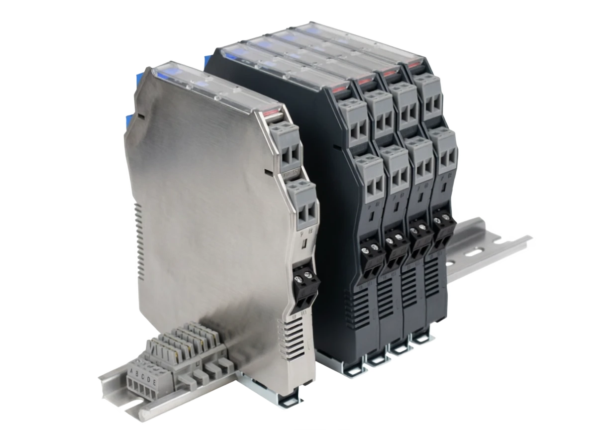
Using 35mm DIN guidance card assembly structure: the narrow long module shell (heavy 12.5-20mm class) can be installed in a special cabinet or system rack at high density and in a separate segment, with a hazard side (this endor, blue) and a security side end partition placed with a separation block, with the barrier transformer being separated into two-side circuits within the module, with the power being introduced by the channel transferor or independent end. The whole machine is designed for natural dispersion without fans and is installed at a high density by the manufacturer's number of side-loads and load drop curves to account for temperature rise.
- 01
2 • Isolation transformer • Core part of the separation fence: enhanced insulation between initial stages (Isolation 1.5 ~ 2.5 kV AC); Share DC/DC with signal two-way mode transfer; (b) The transformer parameters determine the Uo ceiling and transfer accuracy; The filling process ensures the environmental reliability of vibrations
- 02
3 Zina diode / TVS (multi-stage and associated increase of the reliability of the pliers); power-limit current resistance (irrequired essential security element, no failure pattern clear); electronic limit current circuits (reciprocal feature); energy-restricted portion is certified coverage and maintenance is not allowed
- 03
4 Signal circuits . Dangerous side: Transmitters feed / Cold end compensation / NAMUR incentive / linearization; Safety side: Simulation of volume output driver (sourced / passive), relay and transistor switch output; HART Linking Backway (optional); Scale and signal formation (decord or software)
- 04
5 Track and distribution . 35mm DIN Tray Cards; Track Conveyment Distribution (multimodule co-electrical debarment); Redundant power module and decomposition . Binal tubes; Partition line inside the cabinet by Ben/ Non-Ben Ant line (separated block + chute)
Application area
• The area of application
The application revolves around the "low-energy signal loop at the explosive hazard site": the security fence is almost always used to access the equipment that is installed in the explosive hazard area on site and that is intended to enter the security zone control system. Four main categories are grouped by type of signal: analogue detection circuits (transmitters/temperatures), switch detection circuits (NAMUR / dry points), analogue control circuits (valve locator / electric / gas converters), and digital bus and special signals.
- 01
(b) PIC refining devices · Pressure / Flow / LRT 4-20mA return route (in hundreds of thousands of routes); (a) The 4-20mA command circuit for the control valve locator. DCS, with pre-accreditation catalogue type; (a) HART mass formation; Enter and pass to the recorder branch (part 48/53)
- 02
Chemical and fine chemicals Reacting temperature thermoelectric dolls/thermal circuits; pH / conductor analyser simulations; fluid and temperature circuits in tanks; cold end compensation for temperature input barrier bands; order of range and fraction number confirmation; embalming level in corrosion chamber
- 03
Gas and gas storage and long-term transmission. Retardation of liquid levels in storage tanks/serving liquid position loops; (b) Temperature monitoring; • Co / Lo Cable Storage Accounting (long-range focus); Fuel-efficient detectors use Ben Angil Roads; Linked circuit selection with SIL authentication model
- 04
Medicine and biofermentation · Temperature / Pressure / pH return route; Clean Zone flow loop • Simulation of volume separation fences as main; signal conversion (mV ⁇ 4-20mA) requirements are common; small project cabinets are equipped with internal guidance tracks
Selection Guide
• An option guide
The complete description shows the technical sections.
Model Selection SELECT A MODEL
1 Model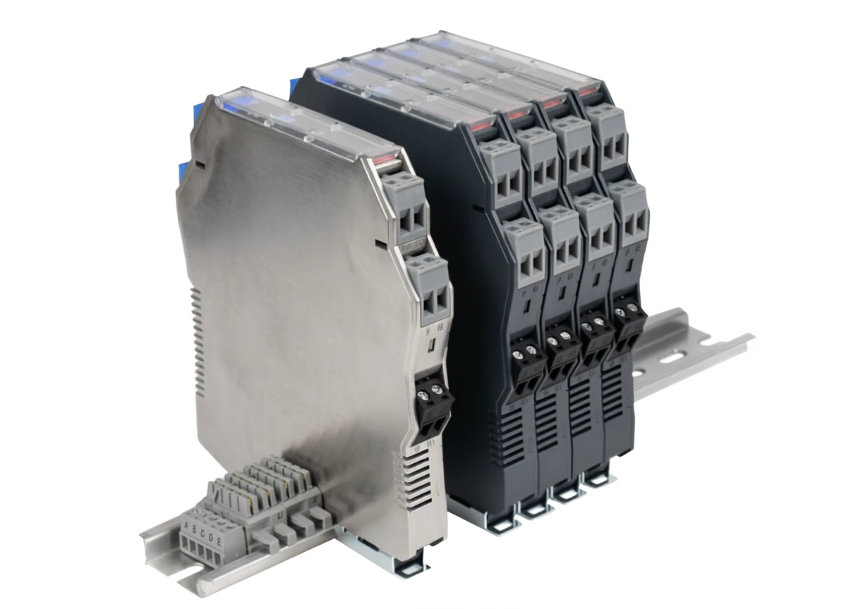
Isolated security fence support
Provide survey missions, media and installation conditions and obtain product configuration advice.
Contact us