PRODUCT TECHNOLOGY

Cone flow count

Operating principle

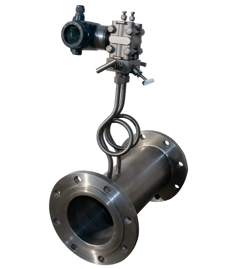
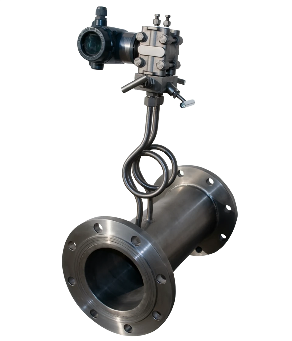
V-Cone flow meters.

Theoretically, the two basic laws governing the flow of fluids in closed pipelines: flow continuity equations (mass constant) Flow measurement tubes with a V-shaped cone installed in the axis, gradually shrinking, speed of flow faster, and still pressure lower, creating differential pressure between the upper and lower sides of the cone (concentrated back): positive pressure (high pressure): the plume extraction vent before the upper fluid shrinkage of the cone; Under stable flow conditions, volume flow in a pipe is proportional to the square root of the differential pressure: Q = C ε (π/4) D² β² √( 2 ΔP / ρ( 1 ) of which: -Q - volume flow; - C — exit factor; - ⁇ - Compressible expansion factor (liquid ⁇ 1); - D —
Reference to the classification of the V-Cone Flows Count
Cone flow count V. Classification reference diagram

V-Cone flow menu support

Provide survey missions, media and installation conditions and obtain product configuration advice.

Contact us
V-cone flow meters . Technical note

TECHNOLOGY & APPLICATION

Understand the principles, the exact selection.

From measurement principles to field applications, the technical characteristics and selection elements of the V-Cone Flow Count are understood.

01

MEASUREMENT PRINCIPLE

Measurement principle

The theoretical basis is the two basic laws of flow in closed pipes.

Equation of continuity of mobility (quality constant)

Benuli equation.

When the flow of fluids is measured, the flow is gradually shrinking, the flow speeds are accelerated, the pressure is down, and the upper and lower sides of the cone are down.

(Coneback) Generates a difference in pressure between

(b) positive pressure (high pressure): measured at the piping barometer before the upper cone fluid shrinks;

Negative pressure (low pressure))

It is measured at the end of the cone towards its downstream direction, at the extraction hole along the axis of the cone centre.

Measurement formulaClick to see the big picture
Q = C · ε · (π/4) · D2 · β2 · √(2ΔP / ρ(1-β4))

Under stable flow conditions, volume flow in a pipe is proportional to the square root of the differential pressure: Q = C ⁇ ( ⁇ ) 4 ) · D² · β² · √( 2 ΔP / ρ( 1 -β⁴))

of which

- Q — volume flow; - C — exit factor; - ⁇ - Compressible expansion factor (liquid ⁇ 1); - D — Pipeline internal diameter; - Beta - Equivalent diameter ratio (beta = ⁇ (1 - d²/D²), d for cones with maximum cross-section diameter; - ⁇ P — differential pressure; - Old — fluid density.

Key mechanisms — boundary layer effect

The formation of boundary layers along the surface of the cone and its effect of "vacuum layers" make the critical current-saving parts of the cone less susceptible to wear and tear and the value of beta can remain constant for a long period of time, thus providing long-term stability and avoiding frequent re-profiling.

Signal stabilizer.

The lower cone produces a small vortex of low frequency, with a low pressure signal fluctuations of only about 1/10 per cent of the perforation plate, and a stable, high resistance to interference.

Self-restructuring.

Conesian constrictive channels have a condensing and mixing effect on upstream flow flows, significantly reducing the requirement for back and back-to-back straight-line requirements.

02

PRODUCT STRUCTURE

Structure

2.1 Basic structure

2.3 Connections and installation forms

Connection Form

(a) French connection (most commonly used), direct welding, pairing, screw connection;

Large-calibre programmes

(a) Insertion (with pressurized openings, unstoppable installation, low cost) for above DN350;

Install flow

Horizontal, vertical (bottom-up), tilted;

Install direct line segment

Upstream 0~3D, downstream 0~1D (D is the pipe inner diameter), with no impact on accuracy either by the single bend or by the double bend of the different plane.

Measurement tube (form)

Note: Measurement tube segments with the same diameter as process pipes, carbon steel/restainless steel/alloy steel

V-shaped cones (scaling)

Note: Pointed cones, with a axis suspended in the measuring tube, fixed through a support frame, is a core throttle element

High pressure extraction.

Note: Upward tube walls of the cone

Low pressure pressure.

Note: At the centre of the cone

Thrust pipe / Triple

Note: High and low pressure to differential deliveryer

Differential pressure transmitter

Note: Conversion of differential pressure to a standard telecommunications number (pressureable, temperature transporter to the temperature reimbursement)

Flow Accumulator / Smart Display

Note: Compensatory calculations performed, showing instantaneous/cumulative flows

Type

Note: Composition

V-collide flow sensor

Note: Only voltage-savings + surfaces, output-pressure differentials, differential-transmitters, etc. are customised by the user

V-Cone Flow Transponder

Note: Sensor + differential transmitter, split / one

V-panometer (integrated)

Note: Sensor + differential/pressure/temperature transporter + smart machine direct output 4-20mA, gas/vapour to achieve temperature compensation

03

TECHNICAL GUIDE

Advantages and disadvantages

3.1 Advantages

The direct section is extremely low.

The first 0~3D, the second 0~1D is fine (the first 10~20D is usually required for the porosity plate) and is an ideal option for the old circuits to be modified and space-limited;

It's more precise, it's more repetitive.

Accuracy ±0.5% ~±1.0%. Repetitiveness is better than 0.1% and signal fluctuations are only 1/ 10 for the perforation plate;

Wide turndown ratio

General 10:1 ~15:1 with a maximum of 30:1 ~50:1 when the parameters are reasonably matched;

Permanent pressure is low.

(b) The same β is only 1/3 ~1/5 for perforation of the perforation plate, with significant energy efficiency in long-term operation;

It's dirty, it's unclogged, it's self-cleaning.

A blow-down design that makes the surface of the cone less susceptible to ash, wall, residual residues and suitable for dirty pollution media such as gas and flue gas;

Long-term stability.

(b) Boundary layer effect protection cones, with beta values remaining constant for a long period, free from maintenance or maintenance at very small amounts and without the need for regular repetition of marking;

Self-remediation and mixing

(b) The adversities of the troposphere are highly adaptable and resistant to upstream bends and valve disturbances;

Temperature-resisting range wide

Pure mechanical structure, resistant to high temperature, pressure, corrosive and vibration;

Medium Adaptive Wide

Liquids, gases, vapours, wet gases, gaseous phases, dust particles media are measurable;

Large caliber range

DN15~DN3000。

3.2 Disadvantages

No direct measurement of mass flow

The essence of the differential volume flow measurement, which requires a temperature compensation (pressure, temperature transporter + amplifier) for the gas/vapour to obtain an accurate mass/specify flow, and the complex composition of the system;

The pressure still exists.

(a) A loss of permanent pressure compared to an unobstructed instrument such as an electromagnetic flowmeter, ultrasound flowometer, although smaller than a perforated plate;

Use limits

Not applicable to wall-like media such as high-heavy oil, resins, and slurries (such conditions may be modified to wedge flow); nor generally not to hygienic sterile conditions;

Relatively high prices

Cone will need to calculate and process beta values by process parameters at a one-time cost above standard porosity;

Dependence on tagging/real flow characteristics

Emission factor C needs to be calculated by the manufacturer software or by current labelling, interchangeability and general utility not as high as standard current-saving devices (the perforation plate is supported by standard geometry such as GB/T 2624 / ISO 5167);

Weak hourly pressure signal for small caliber/microflow

Micro differential transmitters are required to measure accuracy limits;

The maintenance requires a stoppage of the tube.

Pipeline structures need to be replaced with a section once cone damage has occurred (insertion can partially mitigate).

04

APPLICATIONS

Application area

No job recommended

High-heavy oil, resin, slurium (remote walls) lumber; wedge flow; corrosive corrosives requiring special material customization; sanitary sterile conditions; selection of sanitary electromagnetic/mass flow meters.

Metallurgy

Typical applications: high-store gas, coke gas, trans-stored gas metering, flue gas/gas emission monitoring

petrochemicals/chemicals

Typical applications: raw oil, slag oil, finished oil, methanol, ethanol, methanol, ammonia, double-oxygen water, various types of water solution, hydrocarbon gas flow measurement

Energy/gas

Typical applications: natural gas (with wet ≤5%), urban gas, hydrogen, nitrogen and multi-assembly gas measurement

Electricity

Typical applications: saturated steam, overheated steam, main water supply, wind (air) measurements

Municipalities/Environment

Typical applications: sewage, biogas, flue gas emissions, large calibre pipes (insertion)

Pharmaceuticals/food

Typical application: non-hygienic process fluids (not recommended at health level)

Rehabilitation projects

Typical application: measurement of inadequate direct sections, complex service pipelines and additional measures

05

TECHNICAL SPECIFICATIONS

Technical Parameter Table

Technical parameter table · Item / ParametersCross-reference
ItemParameters
Measured mediumLiquid, gas, vapour (wet gas, dirty pollution media, gas fluid)
Nominal pipe sizeDN15 ~ DN3000 (conventional pipeline – DN25 ~ DN1600, greater calibre inserted)
Nominal pressure≤16MPa (Conventional), up to 40 ~ 42MPa (Special Design)
Working temperature40°C ~ 600°C (up to 850°C for special design)
Ambient temperature40℃ ~ 70℃
Relative Humidity5% ~ 90%
Accuracy class±0.5%、±1.0%、±1.5%
RepeatabilityOptimum than 0.1% (0.15% / 0.33% / 0.5% stubs)
Turndown ratio10:1 ~ 15:1 (maximum 30:1 ~ 50:1 after the parameter is optimized)
Renault range.8×10³ ~ 1×10⁷ (widen calibre information is 5×10 ~ 10⁷, depending on the manufacturer)
Equivalent diameter ratio to beta0.45 ~ 0.85 (wide range information 0.3 ~ 0.85)
Straight pipe length requirementsUpstream 0~3D downstream 0~1D
ConstructionFrench, welding, pairing, insertion, special customization
FlowHorizontal, Vertical (bottom-up), Tilt
Structure materialCarbon steel, 304/316L stainless steel, double-skinned steel 2205, Haq alloy C-276, 254 SMO, etc.
Output signal4-20mA, pulse, RS485 (Modbus), HART
Electricity24V DC
Explosive/protectiveExd IIBT4/IICT6;IP65/IP67
Supporting instrumentFragmenters (recommendation 0.2 above), trivalves, needle valves, condensers/created condensers (vapour), pressure/temperators, flow calculators
06

SELECTION GUIDE

Select Table

6.1 Process parameters to be provided for the selection (orders required)

6.4 Example of typical model production (in VS series)

Example:

VS-NN100-C-2-Q-W-3 = V-Cone Flow Calculator, DN100, Cone 304/Cube 304/Franco20#, Gas Measurement, Temperature Compensation, French Connectivity, PN 1.6 MPa.

6.5 Elements of a selection supplement

  1. 01

    Suggested margin values

    The tic differential is appropriate for 10-30 kPa; low-flow differential is not less than 0.5 kPa; and the bi-French differential transmitter is not less than 3kPa;

  2. 02

    Swing speed matching

    Liquids 1~3m/s, gases 5~25m/s, vapour 10~30m/s; flow speeds too low magnification cal. + cal. + beta; flow speed too low + large beta;

  3. 03

    The variance carrier accuracy

    (a) Be not less than level 0.2 to ensure the accuracy of the system level 0.5;

  4. 04

    Package Configuration

    V-cones + differential transporters + trivalves + catheters; gas/vapour with temperature, pressure transporters + flow compressors; steam with condensers;

  5. 05

    Acquiring Parameter Channels

    Prefer to user process parameters or design court differential flow gauge specifications, calculated by the manufacturer for beta values, differential pressure, and range

The final model is determined by comparison with the pressure.

Selecting table . Serial number / ParametersCross-reference
Serial numberParametersDescription/unit
1Name of the detected mediumLiquid/gas/vapour; component (percentage of capacity required for mixed gases)
2Flow rangeMaximum, common use, minimum flow (kg/ h, t/h, m³/h, Nm³/h, indicating work or profile)
3Operating pressure(m) Placing/pressure (MPa); maximum pressure
4Working temperatureMinimum, common, maximum temperature (°C)
5Media density, viscosityStatus/profiling (kg/ m³, Pa.s)
6Pipe ParametersCommonly known as diameter, inner diameter, outer diameter, wall thickness, material
7Allowed stress losskPa (decision beta selection)
8Installation ConditionsHorizontal/vertical, connecting forms (Franc/weld/touch), on-site resistance
9Output and compensation claimsWhether the temperature is compensated, signal output, blast protection requirements
Beta rangeCharacteristicsTypical applications
0.45 ~ 0.60 (minus beta)High differential pressure, high accuracy, high pressure loss.Small flow measurements, high accuracy.
0.60~0.75 (middle β)General BalanceMost regular (recommended preferred)
0.75 ~ 0.85 (Big beta)Low pressure, wide stream.Large flow, dirty/particle-containing media, restricted pressure
Selecting Table . Work Type / Recommended ConfigurationCross-reference
Status TypeRecommended Configuration
Clean liquid/gasSTDV cone, carbon steel/304
Filthy gases such as gas, flue gas, etc.Blocked pressure+ blow-cleaning interface (self-cleaning)
High viscosity/slutLarge beta (0.7 ~ 0.85)+Wireway
Vapour (saturated/overheated)High temperature + condensed tank/cooled condensed ring
Corrosive media316 L / Hapsy Alloy C-276 / titanium / lined to trifluoride
Large caliber (more than DN350)Insertion (enabled with pressure openings)
Selecting table . Bits / CodeCross-reference
BitsCodeMeaning
Basic ModelVSCone flow count
caliberDN15~DN3000Nominal pipe size
Materials GroupACone 304 / Steel Pipe 20# / Frank 20#
BCone 304 / Steel pipe 15Crmo / Frank 15Crmo
CCone 304 / Steel pipe 304 / Frank 20#
DCone 304 / Steel pipe 304 / Frank 304
ECone 316L / Steel pipe 304 / Frank 304
GCone 316L / Steel Pipe 316L / Frank 316L
Media1 / 2 / 3 / 4Liquid / Gas / Vapour / High Temperature Medium
Forms of compensationP / QNo temperature compensation / temperature compensation output
Connection FormL / Wscrew connection / Frank connection
Pressure rating0~60.25 / 0.6 / 1.0 / 1.6 / 2.5 / 4.0 / 6.3 MPa
07

TECHNICAL GUIDE

Comparison with other differential flow meters (summarized)

References

The parameters are based on samples of the products of the manufacturing plants.

Comparison with other differential flow meters (summarized) · Contrast / V cone flow metersCross-reference
ComparativeCone flow countStandard PluginsClassic Manchuria.
Direct liner segment (former/recent)0~3D / 0~1D10~20D / 5D5~10D / 1~5D
Permanent pressureSmall (1/3 ~ 1/5) for perforation platesLargeMin
It's dirty.Okay.Difference (successful)Better.
Precision±0.5%±0.5%~1%±0.5%~1.5%
Turndown ratio10: 1 ~ 15: 1 (up to higher)3:1~5:14:1~10:1
Signal stabilityGood (floating to perforate 1 / 10)BadBetter.
PriceHigherLowHigh (large size)
Level of standardizationPlant calculations/flow-markingInternational/national geometry is availableThere's a standard.