PRODUCT TECHNOLOGY

Spin-in-vortex flow meters

Operating principle

The flowometer of the spin vortex.

(b) Forced rotation, which forms a "compulsive vortex constrictive flow (convene or wing) flow" around the line of the pipe at a high rate of rotation; The vortex then passes through the centre of the pipe, which is being reversed by the throttle, and no longer overlaps with the vortex geometric axis of the pipeline, but converses around a spiral (public) to form the " moving vortex". Q ⁇ K'. (P/ ⁇ T) f (Gas process correction: P for absolute pressure, T for absolute temperature) The frequency of the vortex movementf is proportional to volume flowQ, so that the frequency can be measured to convert the flow. : Turbo Street is the two columns of Carmen Turbo Street that have been cut off from the lower pole; The vortex is a single vortex that is spiraling around the axis, with a physical image and signal characteristics that are completely different. Convert
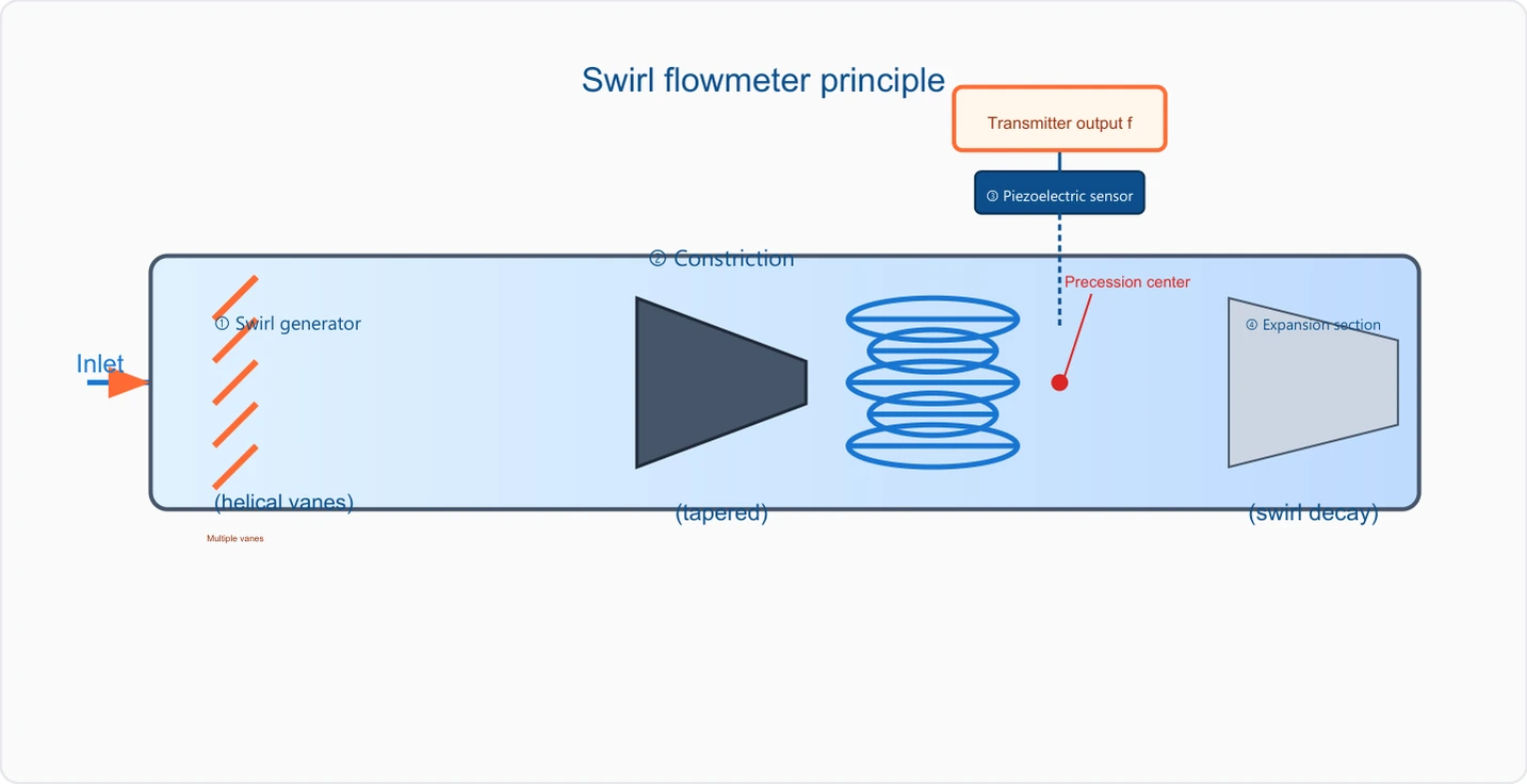
The rotation vortex flow gauges the principle of the flowometer, the converter output f 3 voltage sensor 2 Constriction flowrs 1 in the centre, the vortex generator 4 in the extension segment, the entrance (circle) (circle decay) multi-species
A schematic of the principles of work

Scattering vortex flow meter support

Provide survey missions, media and installation conditions and obtain product configuration advice.

Contact us
• Technical note

TECHNOLOGY & APPLICATION

Understand the principles, the exact selection.

From measurement principles to field applications, the technical features and selection elements of the spiral flow meter are understood.

01

MEASUREMENT PRINCIPLE

Operating principle

Stimulator generator (helium)

Forced rotation, forming a "compulsive vortex constrictive cone or wing" that rotates at high speed around the line

The vortex then passes through the centre of the pipe, which is reversed by the swing, and no longer overlaps with the vortex geometric axis of the pipeline, but is then shaped around a spiral (public) that forms the vortex of the vortex.

Frequency formulaf = K. Q (f for moving frequency, Hz)

Q = f / K (K as instrument coefficient, determined by structure, constant)

Q ⁇ K'. (P/ ⁇ T) f (Gas process correction: P for absolute pressure, T for absolute temperature)

The frequency of the vortex, unlike the vortex flow count,f is proportional to volume flow Q, and the measured frequency allows the flow to be converted.

: Turbo Street is the two columns of Carmen Turbo Street that emerges from the lower column; the spiraling vortex is a single vortex that moves around the axis to spiral, with physical images and signal characteristics completely different.

Converter output f Condensed flow unit (C) Turbo generator extension entrance (swipe)

(Cigre)

Technical IconClick to see the big picture
The rotation vortex flow gauges the principle of the flowometer, the converter output f 3 voltage sensor 2 Constriction flowrs 1 in the centre, the vortex generator 4 in the extension segment, the entrance (circle) (circle decay) multi-species

Multiple key features

Spiral blade force vortex

The entrance must be filled with a spiral of blades and turn straight into a spinning stream, which is fundamentally different from Turbo Street.

Single-in-part vortex

The throttle is followed by a vortex of spiraling center, not a double line of motion.

Pressure detection

Pressure sensors attached to the outer wall of the tube (or embedded in the wall) detect pressure pulses caused by the vortex

Frequency and flow linear

f Q, with a good linear scale and a scale scale of width (1:10 ~1:30)

Force the flow + constrict the flow + the move '(single spiral)'. The structure is accompanied by an entry vortex generator, with a larger constriction of the throttle, a higher frequency level (10 ~ 1000 Hz), and a better measure of the medium-low pressure gas.

  1. 01

    VortexProceion The flow of the spiral is based on

  2. 02

    Solid, principle works. Fluids go through the entrance first.

  1. 01

    The key difference between vortex flow meters.

    "Turk Street is"

  2. 02

    "The Carmon Turbo Street behind the blunt body."

02

PRODUCT STRUCTURE

Structure

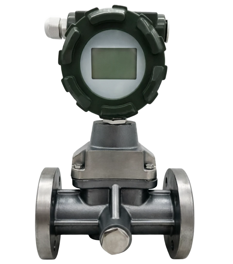
The main tube The rotor vortexometer consists of two components. The main tube contains the vortex generator, the throttle saver, the extension segment and the voltage sensor; the converter is located above or on the side of the tube, and has an amplified circuit, CPU, display and output module.

voltage , vortex in progress, signal line flang spinal blade group fran , extension segment condensed current converter (host)

LCD Display CPU 4-20mARS485 Pulse Temperature pressure reimbursement main component amplification telecommunications, integer count, display of instantaneous and cumulative flow, built-in temperature pressure reimbursement (gas condition), loss 7 converter (host)

4-20mA / RS485 / Pulse

spiral leaf group (Tirion vortex generator)

Function and description: Core component, organized by multiple left or right blades, by a certain yield angle; mandatory fluids generate a strong axis rotation

Progressing Turbo Measurement Segment

Function and description: An equal diameter section downstream of the throttle-savings where the vortex forms a stable spiral motion

Extension

Function and description: Gradual expansion of the export side, which reduces and disintegrates the vortex and avoids downstream disturbance back-flow impact measurement

03

TECHNICAL GUIDE

Advantages and disadvantages

Main strengths

Main limitations

High accuracy of gas measurements

The pressure is much worse.

Precision

Because of forced glitch + contraction

±1.0% ~±1.5%, much higher than normal vortex (gases)

Flows, generating more pressure than Turbo Street (usually 1-5)

Media)

kPa)

Wide turndown ratio

High level of purity required for media

1

10 ~1: 30, wide coverage

Compensation for temperature pressure on the internal pressure of the liquid, when containing particles, oily or gaseous fluid droplets, which is susceptible to jamming leaves or decay

Converter adapts to temperature/pressure-to-temperature signal transmitters, automatically converting to a limited tube path for the profile flow: (Nm³/h) main product DN15 ~ DN200, with a special design structure for larger tubes: no long straight line requirement, long temperature pressure compensation relying on sensors: short, suitable for gas conversion in restricted space must be fitted with a temperature pressure sensor, otherwise the error cannot be moved: long-term stability is good, protection from wear and tear: dust gases are long-term flushing leaves, output functions are abundant: instant/accumulation, periodic temperature/pressure inspection (general 1 ~ 2), 4 - 20mA, RS485, pulses are not subject to high-coinity liquids: liquids are generally used only for low price advantages: they are better than perfluorized, price-coating cleaning bodies (e.g. water, light oils) are less than ultrasound/c.

04

APPLICATIONS

Application area

Pyroscopes, turbines)

Quote the background of the gas and steel industry)

compensation)

Gas production measures (to remove dust)

Gas trade measurement

Gas metering for urban gas gates, business and industry users (and

Compressed Air

Plant compressed air mains, workshop gas measures, energy consumption

Vapour measurement

Saturation steam, superheated steam (required for temperature)

Industrial gases

Industrial gases such as nitrogen, oxygen, americium, carbon dioxide, etc.

High-heavy gas/calorized coal

Chemical gas

Clean water/light oil

Ventilation system

Process gases such as chlorine, ammonia (due to material selection)

Small flow liquid measurements (infinite precision requirements)

Air venting, workshop exhausts, wind, flue gas (with temperature pressure)

05

TECHNICAL SPECIFICATIONS

Technical specifications

A summary of the main technical parameters of the shell carbon steel / stainless steel 304 / 316 L (in media)

Typical flow range of gas conditions (DN15~DN200)

Notes

The above table is based on the condition conditions for air, 20°C, 0.1 MPa; the actual flow of the profile is subject to modification based on the nature of the gas (density, compression factor Z). Gas media are gas, nitrogen, etc., can be approximated by this table.

Technical parameters · Parameter item / specificationCross-reference
Parameter ItemSpecifications
Applicable pipe pathDN15 ~ DN200 (mainstream); selected manufacturers to DN300
Process medium temperature40 ~ 250 °C (up to 400 °C high temperature)
Flow velocity rangeGas 4 ~ 60 m/s; liquid 0.5 ~ 7 m/s
Repeatability±0.2% ~ ±0.5%
Pressure lossAbout 1~5 kPa (by caliber and traffic)
Signal output4-20mA, Pulse, RS485 (Modbus RRU), optional HART
Communications agreementsModbus RRU, optional GRRS / 4G wireless remote
Ingress protectionIP65 / IP67 (dustproof spray)
Technical parameters Common diameter DN / Flow Range (m³/h)Cross-reference
Common Passage DNWorkflow range (m³/h)Profile Flow Range (Nm³/h, 0.1 MPa. 20℃)Working pressure commonly used
DN257 ~ 21055 ~ 1700≤ 4.0 MPa
DN5028 ~ 840220 ~ 6700≤ 4.0 MPa
DN100110 ~ 3300880 ~ 26000≤ 2.5 MPa
DN200440 ~ 130003500 ~ 105000≤ 1.6 MPa
06

SELECTION GUIDE

Selection Guide

Select -step method The key difference between the vortex flow meters is the standard nitrogen/oxygen/silic gas defamin treatment (Oxygen)

Compressed air-energy performance test to convert temperature-compensated mainframe5 The output and communication selection shall be accompanied by temperature-compensating liquids and the recommended preference for electromagnetic or turbines; 2 Gas applications to obtain a physical volume flow; 3 Dust gases shall be pre-empted to avoid foliage; 4 Large pipe diameter (>) DN200 The demand should be changed to turbo street or ultrasound.

⁇ Summary of 2026 Flow Calculator Technology · Swirl Vortex / Vortex Pression Flowmeter = Chapter 6

  1. 01

    1. Identification of the medium gas (main) or low viscosity liquid

  2. 02

    2 Validation DN15~DN200 estimated by flow

  3. 03

    3 Selected pressure level PN16 ~PN64 by condition pressure

  4. 04

    4 Decision on the manner of compensation, temperature or simple

  5. 05

    5 Select output 4-20mA RS485/ Pulse

  1. 01

    Selecting Hints

    One in the vortex flow meters.

  2. 02

    The core advantage is gas measurement (especially natural gas, compressed air, steam), as measured

Selective Guide · Contrast / Spin-Turp FlowsCross-reference
ComparativeSpin-in-vortex flow metersTurbo Street Flow Count (Carmen Turb Street)
Frequency featureSingle frequency, higher (10 ~ 1000 Hz)Double-side alternation, frequency limited by blunt width.
Aerometric precision± 1.0% (high)±1.0%~±2.0%
Applicable pipe pathDN15~DN200 (Small)DN15~DN300+ (More)
Internal Temperature and pressure compensationSpeculation (gas conversion)Not usually. It's a mix.
Media TypeRecommended ModelKey considerations
Compressed air (clean)Standard TypeDescription/Work Double Display
Overheated steamHeat + temperature compensationMust be supplied with temperature/pressure transporter
Selective guidance · Media type / Recommended modelCross-reference
Media TypeRecommended ModelKey considerations
High-bore gas (with dust)Grid-resistant + Pre-depositDust flushing leaves, periodic checks.
Clean water / light oilLiquid-specific typeviscosity ≤ 5 cst, no particles
Nominal pressureSuitable operating conditionsCalvary range
PN25Air pressure, compressed air, industrial gasDN50 ~ DN200
PN64High pressure gas, CNG, high pressure process gasDN15 ~ DN100
ApplicationsCompensation needsRecommended Configuration
Industrial process monitoringThe volume flow is fine.Basic type (no compensation)
Gas long pipelineHigh precision temperature compensation + Z factorHighend Host + High Precision Temperature Transmitter + Flow Computer
Selection Guide . Needs scene / Recommended configurationCross-reference
Demand sceneRecommended Configuration
Flow calculator supportPulse output + RS485
Gas company remote copying4 G/GRRS Wireless Remote + Modbus
Selection Guide . Needs scene / Recommended configurationCross-reference
Demand sceneRecommended Configuration
Data cloud platform accessModbus TCP / MQTT / 4G DTU