PRODUCT TECHNOLOGY

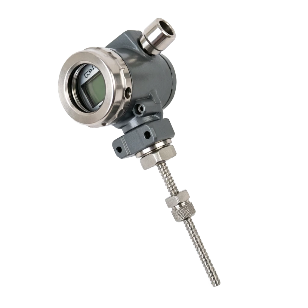
Integrated temperature transmitter

Operating principle

Integrated temperature adapters ..

The core working principle is the "Signal Chain" architecture: a weak analogue signal entered from the sensor, amplified and filtered at the front end (AFE), digitized by ADC, linearization and cold-end compensation of microprocessors (MCU/DSP), digital modelling (DAC) output of 4-20mA streams, superimposed HARTFSK or on-site bus agreements, which eventually achieve two-way communication and diagnosis with the control system. The entire signal chain maintains high precision (typically 16-24 bit ADC) at 1-10 Hz sampling rates, ensuring industrial temperature measurement and control needs. Type 4 simulation input: A thermoelectric doll (mV signal): 8 Class SDD K/N/E/J/T/S/R/B; Thermal Electricity

  1. 01

    1 ~10 modems with oversampling and noise integrator (noise)

  2. 02

    Hz (typically shaping)

  3. 03

    Hz) effectively inhibits frequent work interference.

  4. 04

    1 Physical input . TC MV signal (-10 ~ +80 MV) Original heat voltage ± 0.1 mV

Integrated temperature adapter selection support

Provide survey missions, media and installation conditions and obtain product configuration advice.

Contact us
Integrated temperature adapters Technical Note

TECHNOLOGY & APPLICATION

Understand the principles, the exact selection.

From measurement principles to field applications, the technical characteristics and selection elements of integrated temperature transporters are understood.

01

TECHNICAL GUIDE

Overview

(Integraded / Field-mounted Temperature Transport) is a smart instrument that integrates sensor signal reconciliation, modular conversion, microprocessor linearization, digital modelling, communication protocols and power management into the same on-site shell. It receives a weak input signal from thermal voltage (mV), thermal resistance (mV) or other analogue signals (mV/X), and after internal amplification, filtering, cold end compensation, ITS-90 linearization, it exports 4-20mA current current superheat superheats with a HART digital signal, or field bus signals such as Foundationfieldbus, PROFIBUS-PA, WirelessHART directly with DCS/PLC/SCADA to accurately measure and control the temperature of the industrial process completed.

1.1 Product positioning and value

The core value is to compress the original "sensor + wire box + disk-mounted transmitter" three-part structure to "sensor + integrated table head" two-part, significantly reducing the distance of transmission of signals, and fundamentally addressing the disruption of the thermoelectric doll's mV signal in long-range transmissions and the introduction of thermal electrical resistance to thermal circuits into critical pain points. Compared to the traditional "temperature adapters of split discs", integrated programmes have significant advantages in terms of high signal quality, high interference resistance, ease of installation, high reliability and low maintenance, and have become the mainstream programme in the field of temperature measurement of industrial processes since the 21 century.

1.2 Brief history of technological evolution

Five major stages have passed.

① 1970 The two-line system of the age simulation 4 - 20mA (No communication); ② 1980 Age Two-Direct HART 5 (Include) 1200 bps FSK); ③ 1990 Age HART6 (addition of incident alarms, equipment variables); ④ 2000 Ages HART 7 / Foundation Fieldbus / PROFIBUS-PA (multivariant, diagnostic rich); ⑤ 2010 From the age of the year to the day of the year, the WirelesshaRT 802.15.4 2.4 GHz jump frequency, IO-Link (dot-to-point two-way communication), and based on NAMURNE107 Standard self-diagnostic techniques (forecast maintenance). During the same period, IEC 61508 SIL 2/SIL 3 functional security certification and IEC 62443 industrial network security certification were also introduced.

1.3 Comparative positioning with traditional break-up programmes

Traditional split approach

Sensor ⁇ Wirebox (cold end compensation) ⁇ Tens of metres of compensatory steering ⁇ DDS & CVVC ⁇ system. Integrated programme: Sensor ⁇ Integrated Tablehead (Hand-in-Cool Compensation and Linearization) ⁇ 4-20mA Flowring/ bus control system. From the point of view of signal integrity, the integrated programme moved cold end compensation points and linear computing points to the sensor end, resulting in higher accuracy of cold end temperature measurements (a distance from the arctic heat source), reduced distance of MV signal transmission to zero, and long-line electrical resistance errors compensated by software (elimination of wire resistance), with overall measurement accuracy increasing by about 30% to 50%.

Table 1-1 Global mainstream manufacturers and representative models of integrated temperature transmitters

General description · Serial number / BrandCross-reference
Serial numberBrandTypical ModelMain call.Characteristic positioning
1Emerson / Rosemount644 / 3144P / 848THART / FF / WirelessHARTpetrochemical, high-end electricity markets
2YokogawaYTA610 / YTA710 / YS1700HART / FFProcess industrial integration
General description · Serial number / BrandCross-reference
Serial numberBrandTypical ModelMain call.Characteristic positioning
3SiemensSITRANS TH100/200/300/420HART / Profibus-PASiemens PLC Compassion
4ABBTTH300 / TTR200 / SensyTempHART / FFElectricity and heavy industry
5Endress+Hause riTHERM TM411 / TM131HART / FF / IO-LinkHealth and modularization
6WikaT32.1S / TCT601 / TC10HART / IO-LinkMiddle market / Health level
7Foxboro (Schneider)I/A Series RTT15 / RTT25HART / FFElectricity, chemical process control
8HoneywellSTT3000 / STT700 / STT850HART / DE / FFExperion System Compassion
9National production: Kawa Yi, Trans-Asian, medium controlPDF Smart Transmitter SeriesHART / FF / Profibus-PAMiddle market / Nationally alternative
10National: Woo-Gwang, Tyne, Conte.YT-3xx/ TY-3xx seriesHARTSmall and Medium Items / General Locations
02

MEASUREMENT PRINCIPLE

Operating principle

The core working principle is the "Signal Chain" architecture: a weak analogue signal entered from the sensor, amplified and filtered at the front end (AFE), digitized by ADC, linearization and cold-end compensation of microprocessors (MCU/DSP), digital modelling (DAC) output of 4-20mA streams, superimposed HARTFSK or on-site bus agreements, which eventually achieve two-way communication and diagnosis with the control system. The entire signal chain maintains high precision (typically 16-24 bit ADC) at 1-10 Hz sampling rates, ensuring industrial temperature measurement and control needs.

2.1 Signal input (four types of analogue input)

Usually supports type 4 simulation input

1 thermoelectric doll (mV signal): 8 (a) The standard classification number K/N/E/J/T/S/R/B; 2 Thermal Retardation (Queue Signal): Pt10 / Pt100 / Pt1000 / Cu50 / Cu100 / Ni120 ; 3 direct current voltage (mV): -100 ~ +100 mV (for non-standard TC or oxygen probes); 4-Tracker (twice): 0 ~ 4000 Dots (for non-standard RTD or level-of-width sensors). All inputs are entered through the same set of end-ends, and the internal multiplex (MUX) is configured to switch to different signal adjusters. Thermal voltages share a set of inputs with thermal resistance, but the software is configured to automatically switch gains, stimulate currents and cold-end compensation models according to "sensor type".

2.2 Signal reconciliation (simulation front end AFE)

Analog Frontend End, AFE is a key analogue circuit for the transmitter, with the main function being: 1 instrument amplifier (PGA, programmable gain) 1 ~ 1000 Double: Magnify the mV signal to the ADC input range (typically) ±5 V or 0 ~ 5 V); 2 Low-intensity Filter (LEC) 4 Class Butterworth, cut-off frequency 1 ~ 10 Hz: Depression 50 / 60 Hz work frequency interference and radio frequency interference (RFI); 3 Cold end compensation (CJC): use semiconductor temperature sensors (e.g.) LM35 / AD590 / PT1000 ) Measure the end temperature of the line, the software presses ITS-90/IEC60584 (b) The fraction scale is inversely calculated for cold end errors of the thermoelectric doll and is added to the measurement results in real time; 4 Incentive Power (RTD mode): Provision 0.1 ~ 1 MA constant flow incentive (typically) 0.5 mA (i) Avoiding self-heating; 5 Lead-line electrical resistance compensation (RTD model): Support 2 Linear / 3 Linear / 4 Wireless automatic identification and compensation, of which 4 Wirework eliminates lead-line electrical failure to the point of failure. 0.001 Once in the order of magnitude.

2.3 Model conversion (ADC)

ADC is the core element that determines the accuracy of the transmitter. Integrated temperature adapters are mainstreamed using 16~24 bit Sigma-Delta-type ADC (e.g. TTI ADS 131, AD7190, AD7799) with a resolution of 0.001 °C (Pt100 range) and sampling without noise resolution (Noise-FreeResolution), which is the best current high-precision temperature measure. Some high-end products (e.g. Rosemount 3144P) have adopted a double ADC redundancy structure to further upgrade SIL 2/3 functionality security.

2.4 Microprocessor linearization (MCU / DSP)

The CMU is the "brain" of the transducer, which is responsible for ADC data collection, cold-end compensation calculations, linearization of the ITS-90, conversion of engineering units, output current control, communication contract cages, self-diagnosis and incident alerts. Mainstream MMUs include ARMCortex-M0/M3/M4, TTI MSP430, Microchip PIC24/dsPIC33, Renesas RL78/RX, work frequency 16~200 MHz, Flash 64~512 KB/RAM 8~64 KB/EEPROM 4~64KB (for grouping and labelling data). Linearization algorithms achieve a precise conversion of 0.001 °C resolution using the International Temperature Standard ITS-90 using a multi-stage formula (Callendar-Van Dusen equation or CVD coefficient table) or a search table (LUT).

2.5 Output and communication (DAC/ communication protocol)

The output module converts the digital temperature value from the MMU processing to the 4 - 20mA Direct current signal. Main circuits include: 16 bit DAC +V/I converter (e. g. AD5410 / XTR105 ) . . . .. 4mA and 20mA It's done on two current points. ±0.05% Precision. Communications modules superimpose different protocols according to product positioning: 1HART 7 (Bell 202 FSK 1200 bps superimpose 4 - 20 (mA on); ②Foundation Fieldbus H1(IEC 61158,31.25 kbps); ③PROFIBUS-PA(31.25kbps); ④WirelessHART(IEEE 802.15.4 2.4 GHz DSS frequency; ⑤Modbus RTU( RS-485 , 4 It's only for wires. All communication protocols support equipment descriptions (DD / DTM / EDD) and remote grouping and remote diagnosis.

2.6 Power supply and isolation

Usually 2-wire power supply (most commonly)

The current circuit from 4-20mA, working voltage range 12 ~ 42 VDC (typical 24 VDC), is restricted to 9 ~ 28 VDC in this environment. 4 Wireless products are provided independently: AC85~265 V 50/60 Hz or DC 18~36 V. The power module isolates the input/output/communication 3 road 1500 V AC to ensure non-interference between the live signal, the control room signal and the site. The Ex-ia product also has to meet the IEC 60079 - 11 standard: maximum open voltage Ui ≤ 28 V, maximum short circuit current Ii ≤ 100 mA, maximum power Pi ≤ 1 W.

Table 2-1 Integrated temperature transmitter signal chain workflow (8 steps)

  1. 01

    1 ~10 modems with oversampling and noise integrator (noise)

  2. 02

    Hz (typically shaping)

  3. 03

    5 24

  4. 04

    Hz) effectively inhibits frequent work interference.

Motion of work . Step / Signal phaseCross-reference
StepsSignal phaseMain processingOutput FormPrecision range
1Physical inputTC MV signal (-10 ~ +80 MV)Raw thermal power±0.1 mV
2AFE Zoom inPGA gain 1 ~1000 times ~0 ~5 VMagnify voltage±0.01 mV
3Filter4 Steps Butterworth close to 5 HzWork frequency suppresses signalNMRR ≥ 60 dB
4Cold junction compensationSemiconductor temperature + numerical compensationCold-end fixation temperature±0.1 ℃
5ADC24 bit Sigma-Delta 5 HzNumber±0.001 ℃
6LinearizationITS-90 Polyformat or LUTProject temperature±0.05 ℃
7MPU controlOutput current calculation + communication protocol4-20mA Digital supersing±0.05%
8DAC Output16 bit DAC+V/I conversion4-20mA Electro-ring±0.05%
03

PRODUCT STRUCTURE

Product structure

Designed using Modular structures, consisting of 12 core components, including outer casings, electronic modules, wire terminals, sensor interfaces, communication modules, display modules, etc. The interior of the module is divided into functional 6 large circuit modules: signal input module, signal reconciliation module, ADC module, MMU module, output module, power supply and isolation module. The casings are classified into 4 types by installation: on-site installation type (B / Din B head), track type (D), cabinet type, wall type; The site is installed in the most mainstream structure and is installed directly at the top of the thermoelectric doll/thermal electrical circuit box (DINB head).

Table 3-1 Integrated temperature transporters 12 Structure table for components

Shell / Shell

Main function: Sealed electronic chamber + Provide installation interface Key materials/processes: aluminium alloy cast/ stainless steel 316L failure mode: corrosion, seal failure

Board / Transparency Window

Main function: Protection of LCD + Displaying Number Key Materials/Processs: PC Polycarbonate + Aluminium Alloy Fault Mode: Old Flower, Leak Light

Connector End

Main function: Connecting sensors to power supply Key material/process: Nickel-plugged brass + screwdriver Fault mode: loose, oxidized

Cold end compensation sensor

Main function: Measuring end temperature of the line key material/process: LM35 / AD590 / Pt1000 Fault mode: drift, breakline

Instrument amplifier PGA

Main function: mV signal amplification Key material/process: INA 128 / AD620 Fault mode: disorder, saturation

Low-link filter

Main function: Repression frequency and RFI key materials/processes: RC source filtering Fault mode: cut-off frequency offset

ADC Model Converter

Main function: Simulation of signal digitization Key material/process: AD7190 / ADS131 Fault mode: quantitative error, noise

MMU microprocessor

Main function: linearization and communication control Key material/process: ARM Cortex-M4 failure mode: program flight, reset

EEPROM / Flash

Main function: Maintaining the grouping and marking key materials/processes: I2C / SPI interface Fault mode: data loss, writing failure

DAC Numeric Modeller

Main function: Digital transfer 4-20mA Key material/process: AD5410 / XTR105 Fault mode: current deviation, drift

Communications module

Main function: HART / FF / PA Protocol Key materials/processes: HART Modem A5191HRT failure mode: communication failure

DC-DC power isolation

Main function: Input and output segregation of power supply Key material/process: transformer + DC-DC module Fault mode: short circuit, pass through

Circuit module

Signal Input Module

Main component: MUX Multi-Range Reuse + Overcrowded TVS Key function: Switch TC/RTD/mV/Drive Performance indicator: Enter to resist ≥ 10 M (TC)

Signal reconciliation module

Main component: PGA + filter + CJC + Incentive source Key function: Magnification, filtering, cold-end compensation, incentive performance indicator: CMR ≥ 80 dB, NMR ≥ 60 dB

ADC Module

Main shape: 24 bit Sigma-Delta+ Baseline Source Key function: high accuracy model conversion Performance indicator: active bit ≥ 21 bit (5 Hz)

MPU Module

Main component: ARM Cortex-M4 + Flash + EEPROM Key function: linear, grouping, communication, diagnostic performance indicator: main frequency ≥ 64 MHz, Flash ≥ 256 KB

Output Module

Main component: 16 bit DAC + V/I + HART Modem Key function: 4-20mA + HART FSK Performance indicator: ± 0.05% current accuracy, HART 7

Power module

Main component: DC-DC isolation + LDO + EMC filter key function: input-out-segregated power supply performance indicator: isolation ≥ 1500 V AC, texture ≤ 30 mV

Shell type

Field installation type (type B / Din B)

Outer characteristics: Cylinder shape 80 × 80 mm Head, bottom. M24 × 1.5 Threads Installation: Directly screwd over the top of the thermoelectric doll/thermal electrical circuit box Typical applications: petrochemical reaction plume, power plant owner, steam, gas and gas.

Track type (D / DIN Railway)

PHYS: thin rectangular 100 x 25 x 100 mm installation: DIN 35 mm track (in the DCS cabinet)

Airbox / Disk

Exterior feature: Standard 1/4 DIN or 1/8 DIN panel Installing: Disk open-face embedded installation Typical application: Control room display and operation

Mini Head

Apparel: miniaturized ⁇ 45x40 mm compact surface installation: M24x1 internal screws installed at the top of the sensor Typical application: space restricted narrows, sanitary site

04

TECHNICAL GUIDE

Advantages and disadvantages

The dominant programme in the temperature measurement of industrial processes has a significant advantage over conventional break-down disk carriers, but there are inherent deficiencies such as environmentally sensitive temperatures and the restriction of Ben-Ann electricity supply, which need to be weighed against the project selection.

4.1 Main advantages (8 grand)

4.1 Main advantages (8 grand)

Signal integrity high

Details: mC signal transmission distance reduced from tens of metres to zero, avoiding long-line interference and lead-line electrical resistance error

It's a good intervention.

Detailed: Sensitive analogue signals are digitized locally, superseding HART/FF Total immunity after digital communication RFI/EMI

Install Easy

Detailed: Integrated sensor + transmitter design, saves the repair of the steering and filing cabinets, reduces the installation workload by 60%

It's a rich diagnostic function.

Detailed: Supporting NAMUNE 107 status classification, sensor break-through/short-circuit detection, drift from diagnosis, predictive maintenance

Remote group capabilities

Detailed: Remote parameter setting and upgrading through HART / FF / PA handheld or asset management system (AMS)

Multivariate Measurement

Detailed: Output temperature + cold temperature + sensor health + self-diagnostic code (maximum 4 variables)

Cold end reimbursement is accurate.

Detail: Move to the on-site end end temperature measurement point to avoid thermal-source effects of the cabinet, compensates accuracy ± 0.1 °C

Explosive/protective integration

Detailed: Design integrated with the electronic module, simplified on-site wiring, consistent with IEC 60079 / IEC 60529

Disadvantages and use restrictions

Temperature sensitive

Detailed: work temperature of the electronic module -40 ~ +85 ℃, needing shielding or selection of division options beyond range

Bennan's power supply is limited.

Detailed: 2 line-based circuits Ui ⁇ 28 V / Ii ⁇ 100mA / Pi ⁇ 1 W, long distance power supply requires verification of cable parameters

Maintenance inconvenient

Detailed: Locations of installation on site are usually on high or pipe, replacement or marking is required for shutdown or height operations

High blast/protection costs

Detailed: Ex d) shell cost about 2000~5,000, 3~5 times more than normal

Short-term marking period

Detailed: High-precision product (±0.05 ℃) needs to be marked annually or every 2 year back to the plant, with higher maintenance costs

Communications protocols are not interoperable.

Detailed description: Different manufacturers DD/EDD/DTM are not fully compatible and multi-plant mixing requires caution

Work-use limit

Detailed: 2-line 24V/4mA 96 mW, WirelessHART only need battery power, 5-10 years of working life

05

APPLICATIONS

Application area

The use of petrochemicals, electric energy, metal and steel, medicinal organisms, food beverages, paper making, water treatment, aerospace, marine engineering, new energy sources, semiconductor manufacturing, etc. is widespread in almost all industrial processes. The requirements for precision, blast protection, protection and communication agreements vary significantly from industry to industry, requiring the selection of appropriate product specifications based on specific conditions.

Table 5-1 Integrated temperature adapters 14 Large typical application scenarios

Petroleum chemicals

Typical temperature scenarios: Reaction plume, distillation tower, crack furnace Temperature range: 200 ~ +900 ℃ Key requirements: blast protection + high accuracy + HART

Electricity and energy

Typical temperature scenario: boiler main steam, steam engine, water temperature range: 50~+650°C Key requirements: high pressure + vibration resistance

Metal and metal

Typical temperature scenarios: furnace roofs, transformers, binding crystals Temperature range: 0 ~ +1700 ℃ Key Requirements: High temperature tolerance + Rapid response

Medical organisms

Typical temperature scenes: fermentation tanks, fungic scavengers, cool dry temperature ranges: 80 ~ +150 ℃ Key requirements: sanitary + surface polishing

Food and drink

Typical temperature scenario: CIP washing, papsis, filling line Temperature range: 20 ~ +200 ℃ Key requirements: IP69K + EHEDG authentication

Paper industry

Typical temperature scenes: baking tanks, coating machines, dryer tanks Temperature range: 0 ~ +300 ℃ Key requirements: tideproof + long distance

Water treatment

Typical temperature scenarios: sludge digestion pool, exposure pool, water contamination temperature range: 10 ~ +100 ℃ Key requirements: IP68 water protection + corruption protection

Aerospace

Typical temperature scenario: engine burn chamber, hydraulic oil temperature range: 50~ + 1200°C Key requirement: impact resistance + vibration resistance

Marine engineering

Typical temperature scenarios: LNG storage tanks, ship hosts, seaboard platforms Temperature ranges: 196 ~ +500 ℃ Key requirements: salt fog preservation + classification society certification

New energy

Typical temperature scenario: battery packs, battery heat management, storage capacity Temperature range: 40 ~ +150 ℃ Key requirements: CAN bus + high insulation

Semiconductor

Typical temperature measure scenario: dispersors, CVD, expanse temperature range: +200 ~ +1200 ℃ Key requirements: ultra-purity + particle control

Nuclear power

Typical temperature scene: A roadmaster, steam generator Temperature range: 50~+650°C Key requirements: earthquake resistance + safety + 1E

Long run of gas.

Typical temperature scenarios: pipelines, tanks, LNG stations Temperature range: 196 ~ +500 ℃ Key requirements: Ex d + Long Distance + WirelessHART

Warming HVAC

Typical temperature scenarios: cold heat sources, air conditioners, wind heat pumps Temperature ranges: 50 ~ +150 ℃ Key requirements: low cost + common protocol

Precision requirements

Petroleum chemicals

Precision requirements: ±0.1 ℃ blast protection level: Ex ia/d IIC communication protocol: HART / FF typical temperature range: 200 ~ +850 ℃ preferred model series: 644 / TTH300

Electricity and energy

Precision requirements: ±0.2 ℃ blast protection level: Ex ia IIB communication protocol: typical temperature range for HART: 50 ~ +650 ℃ preferred model series: 3144 P / YTA610

Metal and metal

Accuracy: ±0.5 ℃ blast protection level: No / dust protection protocol: HART / Wireless typical temperature range: +800 ~ +1700 ℃ preferred model series: TTR200 / YS1700

Medical food

Accuracy: ±0.1 ℃ blast protection level: No / Health Communication Protocol: HART / IO-Link Typical Temperature Range: 80 ~ +200 ℃ Preferred Type Series: TM411 / T32

Marine nuclear power

Precision requires: ±0.05 ℃ Explosive-proof level: Ex d/ 1 E-class Communications protocol: HART / FF typical temperature range: 196 ~ +650 ℃ Preferred Model Series: 848 T / RTT15

06

TECHNICAL SPECIFICATIONS

Technical Parameter Table

Table 6 - 1 Integrated temperature adapter 23 Table of the entire machine parameters 6 - 2 Integrated temperature adapter 8 Class input signal comparison table 6 - 3 Integrated temperature adapter 7 Comparison of communication agreements

Technical parameter table . Serial number / parameter itemCross-reference
Serial numberParameter ItemSpecificationsTypical values/ranges
1Input signalTC +RTD + mV + Multiple TypeClass 8 TC + 6 RTD + mV + times
2Thermocouple typeIEC 60584 Standard ScoreK / N / E / J / T / S / R / B
3Thermal resistance typeIEC 60751 + Industrial standardPt10 / Pt100 / Pt1000 / Cu50 / Cu100 / Ni120
4Temperature rangeDepending on the type of sensor270 ~ +1820 ℃
5Measuring precision (Pt100)Level A ± 0.15 °C / Level B ± 0.3 °C±0.05 ℃ / ±0.1 ℃ / ±0.2 ℃
6Measuring precision (K TC)Typical 0.5 °C or 0.4% FS±0.5 ℃ / ±0.3 ℃ / ±0.2 ℃
7ResolutionPt100 Full Scale 0.001 °C16~24 bit ADC
8Sample RateSetable 1 ~10 HzTypical 5 Hz
9Output signal4-20mA + Digital communications4-20mA + HART 7 / FF / PA / Wireless
10Output current accuracy4mA / 20mA Two o'clock. ±0.05%±0.05% / ±0.1% / ±0.2%
11Communication protocolsHART / FF / PA / ModbusHART 7 / FF H1 / PA / Modbus RTU
12Electricity voltage2 Liner 24 VDC (typical)12~42 VDC / 18~36 VDC (4 line)
13This Angular Parameter (Ex ia)IEC 60079-11 RestrictionsUi≤28V、Ii≤100mA、Pi≤1W
14Work2-linear model 3.5 MA3~21 mA
15Isolation intensityInput/output/power 3 Segregation1500 V AC / 1 min
16Explosion protection markingBenam/ Detonation / DustEx ia/d IIC T6 / Ex tb IIIC T80℃
17Ingress protectionIEC 60529 StandardIP65 / IP66 / IP67 / IP68
18Working temperatureTemperature of the electronic chamber environment40 ~ +85 ℃
19Storage temperatureTransport and storage temperature55 ~ +105 ℃
20Relative HumidityWork moisture (non-cooled)0~95% RH
21EMC ResistanceIEC 61326-1 Industrial environmentCriterion A (accidental action)
22Functional securityIEC 61508 SIL authenticationSIL 2 / SIL 3
23MTBFAverage no-facilities time≥ 1000000 hours (typical)
Technical Parameter . Type / SignalCross-reference
TypeSignalPunctuation / TypeTemperature rangeTypical precisionIncentives/inputs to resist
TCmVType K270 ~ +1372 ℃±0.5 ℃ / 0.4%FSEnter block ≥ 10 M times
TCmVType N270 ~ +1300 ℃±0.5 ℃ / 0.4%FSEnter block ≥ 10 M times
TCmVE/ J/ T270 ~ +870 ℃±0.3 ℃ / 0.4%FSEnter block ≥ 10 M times
TCmVS/ R type50 ~ +1768 ℃±1.0 ℃ / 0.4%FSEnter block ≥ 10 M times
TCmVType B0 ~ +1820 ℃±1.0 ℃ / 0.4%FSEnter block ≥ 10 M times
RTDΩPt100 / Pt1000200 ~ +850 ℃± 0.1 °C (A level)Incentive 0.5 MA
RTDΩPt10 / Cu50 / Ni120200 ~ +850 ℃±0.3 ℃Incentive 0.5 MA
mV / Ω100~+100 mV / 0~4000 ΩUniversal InputA random marking±0.05%FSThe incentive is right.
Technical parameter table · Protocol / Physical layerCross-reference
AgreementsPhysical layerTransfer rateTakahumi!Maximum number of devicesTypical applications
HART 7FSK superseding 4-20mA1200 bpsPoint to Point / More1 ~15 NodeMainstream field bus
Foundation Fieldbus H1IEC 6115831.25 kbpsbus/ treeParagraph 32/ busLarge DCS projects
PROFIBUS-PAIEC 6115831.25 kbpsbus/ treeParagraph 32/ busSiemens PLC System
WirelessHARTIEEE 802.15.4250 kbpsMesh Net100 Nodes/GateHard to line up.
Modbus RTURS-4859.6~115.2 kbpsbus/ star247 Node/ bus4 Lined Settings
IO-LinkIEC 6113138.4 kbpsPoint to Point1 Host 1 DeviceDispersed manufacturing / equipment
PROFINETIndustrial Ethernet100 MbpsStar/ TreeHundreds of nodes.Plant automation
Type of blast protectionCodeArea of applicationProtectionTypical locationShell requirements
Essentially safeEx ia / ib / icZone 0/1/2Limit EnergyField bus, battery powerAluminium alloy / stainless steel
DetonationEx d IIB / IICZone 1/2Separating the blast flames.Refining, chemical tank areasthick wall casting / Frank
AddedEx eZone 1/2Fire and temperature.Operators, helpersStrengthen insulation
Positive pressureEx pZone 1/2Blowing the inert gas.The cabinet, the PLC station.Condensed + Pressure Control
Dustproof.Ex tb / tcZone 21/22- It's a little dust-proof.Coal powder, flour, milk powder.IP65+ Dustproof
Oil impregnatedEx oZone 1/2Soaked, cooled.Transformers, high power equipmentTank + Seal
SealEx mZone 1/2Zoom inSmall components, relaysepoxy resin seal
07

SELECTION GUIDE

Select Table

The selection forms are presented by type of input, mode of output, level of blast protection, and level of protection, by 4 dimensions, respectively, 11/5/ 6/ 6 row control tables, which allow engineering designers to systematically select according to temperature objects, control system interfaces, hazard areas on site and environmental conditions.

Table 7-1 Table of type of input for integrated temperature transmitters (11 rows)

4-20mA+HART7 dual-line current ring 1200bps Main field bus F sounding FieldbusH1 bus cable

  1. 01

    25kbpsPROFIBUS-PA bus cable

  2. 02

    25kbps West Gate PLC/PCS7WirelshaRT

  3. 03

    4 GHz wireless 250 kbps hard-wire, rotation equipment ModbusRTURS-4854 line WikaT32 / national model table 7 - 3 Integrated Temperature Carrier blast-proof grade sheet (6 row)

Select Table . Type / SignalCross-reference
TypeSignalFraction / SpecificationTemperature rangeTypical applicationsRecommended Model
TCmVType K270~+1372 ℃General-purpose high temperature, power plants, metallurgy644 / TTH300
TCmVType N270~+1300 ℃Power plant overheater3144P / TTR200
TCmVType E270~+870 ℃Low temperature, low electrically transmitted medium644 / TM411
TCmVType J210~+760 ℃Old equipment, retrofitting atmosphere644 / T32
TCmVType T270~+400 ℃Temperature, medicine, foodTM411 / T32
TCmVS/ R type50~+1768 ℃High temperature furnaces, catalytic fragmentationTTH300 / TTR200
TCmVType B0~+1820 ℃Super-heat furnaces, glass kilnsTTH300 / 848T
RTDΩPt100200~+850 ℃Main medium- and low-temperature programmes644 / T32 / TM411
RTDΩPt1000200~+600 ℃Respond quickly, and be sensitive.TM411 / T32
RTDΩCu50 / Cu10050~+150 ℃China's old electricity standardNationally produced series / Kawasi
mV / Ω100~+10 0 mV / 0~4000 ΩUniversalA random markingNon-target sensors, bits848T / TTH300
Output MethodTransfer mediaCommunication rateTypical applicationsRepresenting products
4-20mA + HART 7Double-wire current ring1200 bpsMainstream field busRosemount 644 / Yokogawa YTA610
Foundation Fieldbus H1Cable cable31.25 kbpsLarge DCS / Emerson DeltaVRosemount 3144P / ABB TTH300
PROFIBUS-PACable cable31.25 kbpsSiemens PLC / PCS7Siemens SITRANS TH300
WirelessHART2.4 GHz Wireless250 kbpsHard-to-wire, rotation equipmentRosemount 848T / 3144P Wireless
Modbus RTURS-485 4 Line9.6~115.2 kbpsPower SCADA / 4 Lined PlacesWika T32 / National Production Model
Selective Table · Explosive/Applicable AreaCross-reference
Explosion protection markingArea of applicationMedia TypeProtectionRecommended programme
Ex ia IIC T6Zone 0/1High-risk gases such as hydrogen, acetylene, etc.Essential security + limited energyIA Level + Separation Fence
Ex ib IIC T4Zone 1Flammable gasesEssential security (plant level)IB Level + Associated Device
Ex d IIC T6Zone 1/2Refining, chemical tank areas- I'm gonna blow the shell.The thick wall casts the shell.
Ex e IIC T4Zone 1/2Support equipment, connect boxesIncreased temperature protection- Increased insulation shell.
Ex tb IIIC T80℃Zone 21/22Coal powder, flour, milk powder.Powderproofing Pov65+Dustproof outer casing + Seal
No blast-proof.Plant safety zoneGeneral industrial settingsNormal IP65/IP67Economic shell
Ingress protectionDust-proof levelWaterproof levelTypical applicationsTypical environment
IP54Dustproof (limited intrusion)Splashproof.Indoor generalThe factory, the control room.
IP65Full dustproof.Low pressure water columnOutdoor generalThe factory's open, near the equipment.
IP66Full dustproof.Strong water column.Scratch EnvironmentFood factory washroom, outdoors
IP67Full dustproof.Short-lived 1 mWet, temporary immersion.Trench, wet zone
IP68Full dustproof.Keep it drenched.Underwater, underground.Groundwater ponds, oil tank monitoring
IP69KFull dust protection + steam cleaning80 °C pressure water washFood / Medical Health LevelCIP Cleaning, Bacillus Ficide
08

SELECTION GUIDE

Selection Guide

8.1 10 Step-style process

8.3 Integrated temperature adapters 10 Line Selection Decision Tree

This summary covers all key technical points of integrated temperature transporters from their rationale to their engineering applications, and the specific selection should be accompanied by a detailed demonstration of the latest product manual for the manufacturer (DD/EDD) and the field work situation.

Selection Guide · Steps / SelectionCross-reference
StepsSelect contentKey decision-making points
1Confirm temperature-detection object and sensor typeTC / RTD / mV / Ω
2Determine temperature range and accuracy levelsPt100 A level ±0.15 °C / K type ±0.5 °C
3Select the shell structure and installationB Head / Track / Mini
4Determine output signal and communication protocols4-20mA+HART / FF / PA / Wireless
5Confirm blast and protection levels.Ex ia/d / IP65/IP67/IP68
6Verify power supply and Ben-An parametersLine 2 24V / 4 Line AC/ Battery
7Confirm ambient temperature and EMC requirements40~+85 ℃ / IEC 61326
8Verify functional security level SILSIL 2 / SIL 3
9Consider diagnostic and remote grouping needsHART 7 / WirelessHART / NE 107
10Spare parts and life-cycle costsStandardized cycles, spare parts supply, training
ComparativeIntegrated temperature transmitterDisc-mounted transceiver
OrganisationOn-site sensor headControl room cabinet board
Signal transmission distancemV signal distance≤ 1 mMV signal distance 30~100 m
Interference resistanceStrong (digitized locally)Weakness (long-line interference)
Cold end compensation accuracyHigh (reimbursement on site)Medium (closure, greater error)
Queue wire electrical resistance errorSoftware reimbursement (4 wire elimination)It's a manual compensation.
Installation workloadSmall (no compensation for lead)Large (reparation of steering and cabinet)
Maintain easeMedium (to stop production and high)High (direct replacement in cabinet)
Working environment temperature40~ + 85 °C (limited to the site)0 ~ +50 ℃
PriceMedium (1500 ~ 5000 CNY)Low (500-2,000 CNY)
Typical applicationsPetrochemical reaction, main steam of the power plantControl room focus on display and control
Selection RecommendationsHigh precision / Remote Location PriorityConsole Shows the scene
Selective Guide Problem / Yes Decision-makingCross-reference
ProblemYes, it's a decision.No. Decision-making
Q1 Temperature range > +500 °C?Select TC (K/N/ S/ R/ B)Select RTD (Pt100)
Q2 needs a remote grouping?Choose HART/ FF / PASelection 4-20mA
Q3. Is there flammable gas on the scene?Select Ex ia / Ex dSelect Normal IP65
Q4. Installed outside?Choose IP66 / IP67IP54 / IP65
Q5 temperature accuracy requirement ±0.05 ℃?Select level A Pt100 + 24bit ADCB-level Pt100
Q6 Conn/Clock Distance > 100 m?Select Integration (shorter mV distance)Selective shape or integration
Q7 Requires a predictive maintenance?Select HART 7 + NE 107Choose HART 5 or pure 4-20mA
Q8 Rotating or moving devices?Choose WirelessHaRT.Select cable 4-20mA+HART
Q9 functional security. SIL 2/3?Select SIL Authentication ProductSelection of general industrial level
Q10 Health level (food/ medicine)?Select EHEDG / 3A + IP69KOptional generic IP65/IP67
Selection guide · Serial number / AttentionCross-reference
Serial numberAttentionDetailed description
1Install Location SelectionAvoid strong magnetic field, strong vibration, heat radiation source, and prioritize the 5D behind 2D in front of the pipe bend
2Temperature limit in the environment≤ 85 ℃ working temperature of the electronic module, exceeding the required heat shield or water cooler
3Thermal tube insert depthEnsure that the temperature measurement end is located at 1 / 3 in the centre of the pipe, with a minimum insertion depth ≥ 100 mm
4Compensatory route selectionTC type must be accompanied by a compensatory guide (KX/ NX/ EX/ SC/RC) with a corresponding fraction
5RTD ThreadsPriority 3 or 4 lines to avoid lead-wire resistance errors from 2 lines
6Block and ground.Compensatory guidance and signal cables must be shielded and shielded at single points (to the control room)
7Seal with Gran's head.The cable entrance is sealed with a blast-proof Glen head and the unused entrance is blocked with metal.
8Electricity voltage Validation2 wired voltage ≥ 12 V, ring load ≤ 600 times (HART mode)
9Validate this Ant-AparsAssociated device parameters Ui / Ii / Pi must be ⁇ security fence limits
10HART Line PolarityHART communication is not sensitive to polarity, but it is suggested that the UTs be harmonized.
11Mine and flood controlInstallation of wave protections (SPDs) outside of the house to resist ≤ 4 every time
12Show module orientationLCD display module should be oriented towards the patrol channel to allow reading on site
Selection guide · Serial number / Maintenance itemCross-reference
Serial numberMaintenance projectsCycleContentsExecutor
1Appearance CheckMonthlyShell, seal, Glen Head, LCD Display, CorrosionField inspector.
2Connector end is strong.Every 6 monthsScripts, wires, cable entrances.Meter maintenance
Selection guide · Serial number / Maintenance itemCross-reference
Serial numberMaintenance projectsCycleContentsExecutor
3Cold-end compensation verificationEvery 12 monthsUse standard TC input against field temperature, error ≤ 0.5 ℃Instrument Engineer
4Overall precisionEvery 12-24 monthsVerify with standard TC / RTD source + HART handheld and return to factory if necessaryVendor or third party
5- Bombproof shell check.Every 12 monthsThe blast zone, the seal, the tight-set twister.Bomb tester.
6Battery replacement (Wirele ss)Every 5-10 yearsWirelessHART when battery capacity is less than 20%Field maintenance officer