PRODUCT TECHNOLOGY

Single-crystal silicon pressure transmitter

Operating principle

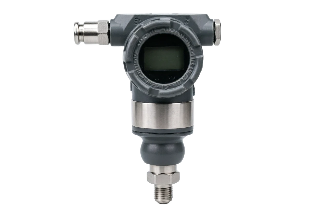
Single-crystal silicon pressure transmitter ..

Single-crystal silicon resistance means that when the single-crystal silicon material is exposed to external force, the stress within the crystal creates a reaction that results in changes in the transport rate and concentration of the carrier, and hence in the resistance rate. The MeMS process is used to spread over single-crystal silicon membrane into 4 P or N types of electrical resistance, forming the Whistlen bridge-wide circuit. When the silicon film is slightly transformed by pressure, the arm of the bridge is subject to a change in electrical resistance, the bridge is unbalanced and the output is linear. Capable single-crystal silicon components consist of single-crystal silicon film and glass or silicon base formations that make up a variable electrical capacitor. Silicon film causes a small shift in pressure, resulting in changes in the PPE spacing and the resulting change in the capacity. The measured pressure can be obtained by testing the capacitation changes through the ASIC chip. Capacitability programs are less sensitive to temperature and long term

  1. 01

    1 The detected medium provides a primary pressure signal

  2. 02

    2 Separating film (optional) • Protection of single crystal silicon sensitive elements and isolation of corrosive media

  3. 03

    3 Filling fluid (optional) . Transmitting pressure to a single crystal silicon chip (demonial structure only)

  4. 04

    4 . Single crystal silicon sensitive element . Converting pressure to telecommunications (pressure/ capacitation)

Single-crystal silicon pressure transmitter selection support

Provide survey missions, media and installation conditions and obtain product configuration advice.

Contact us
· Technical Note

TECHNOLOGY & APPLICATION

Understand the principles, the exact selection.

From measurement principles to field applications, the technical features and selection elements of single-crystal silicon pressure transmitters are understood.

01

TECHNICAL GUIDE

Overview

A high-precision industrial pressure instrument using a single crystal silicon sensitive chip as a core measurement element. The single crystal silicon material has excellent elastic response properties, is almost mechanically slow and has a small temperature coefficient, which is considered to be one of the most accurate and stable stress sensitive materials at present.

This product uses integrated single-crystal silicon pressure resistance or electric-capable sensitive components, which directly convert media pressure to high-notice telecommunications, and which, after a magnification by ASIC, temperature compensation and non-linear correction, output 4-20 ma-current signals and superimpose HART communication protocols. With the high accuracy of ±0.04% FS ~ ± 0.075% FS and the long-term stability of ± 0.1% FS / 5-10 years, single-crystal silicon pressure transmitters have become the preferred option for high-end pressure measurements in the fields of petrochemicals, electricity, metallurgical, metrology and so forth.

This document will provide a systematic description of the rationale, structure composition, comparison of strengths and weaknesses, application areas, technical parameters and guidance on selection, which will provide a reference basis for engineering design and equipment selection.

02

MEASUREMENT PRINCIPLE

Operating principle

2.1 Single-crystal silicon pressure resistance effect

Single-crystal silicon resistance means that when the single-crystal silicon material is exposed to external force, the stress within the crystal creates a reaction that results in changes in the transport rate and concentration of the carrier, and hence in the resistance rate. The MeMS process is used to spread over single-crystal silicon membrane into 4 P or N types of electrical resistance, forming the Whistlen bridge-wide circuit. When the silicon film is slightly transformed by pressure, the arm of the bridge is subject to a change in electrical resistance, the bridge is unbalanced and the output is linear.

2.2. The single-crystal silicon-composible principle

Capable single-crystal silicon components consist of single-crystal silicon film and glass or silicon base formations that make up a variable electrical capacitor. Silicon film causes a small shift in pressure, resulting in changes in the PPE spacing and the resulting change in the capacity. The measured pressure can be obtained by testing the capacitation changes through the ASIC chip. The programme is less sensitive to temperature and more stable in the long term, but more complex in the circuits.

2.3 Signal processing and output

The micro-discretion voltage (or the electrical capacity signal) of the bridge route output is multi-level amplified by a dedicated ASIC chip, temperature compensation (PTAT circuit and multi-point calibration), non-linear correction and digitization, converted to 4-20 MA standard industrial signals through DAC and superseding HART 7 digital communications. Some high-end models also support live bus agreements such as FOUNDATION Fieldbus, PROFIBUS-PA.

2.4 Pressure transfer pathways

Page 3, page 4

Motion of work . Serial number / chainCross-reference
Serial numberLinkFunctional description
1Media testedProvides raw pressure signals
2Separating film (optional)Protection of single-crystal silicular sensitive elements, isolation of corrosive media
3Filling fluid (optional)Transfer pressure to single-crystal silicon chips (demonial structure only)
4Single-crystal silic sensitive componentConvert pressure to telecommunications (pressure/ capacitation)
The working principles 5 / ASIC magnifying circuitsCross-reference
5ASIC Zooming in.Signal amplification, temperature compensation, linearization
6Output signal4–20 mA + HART / FF / PROFIBUS-PA
03

PRODUCT STRUCTURE

Product structure

3.1 Typical structural composition

It can be divided into two types: "direct contact" and "divestment" with a compact, responsive structure;

Membrane is used for mediums such as corrosive, crystallizable and corrosive.

3.2 Direct contact and diaphragm contrast

3.3 Typical structural illustrations (text description)

Direct contact type

Process connection (1) ⁇ Single crystal silicon sensitive element (4) ASIC magnification circuit (5) ⁇ wiring endpoint (9) ⁇ shell (7).

Imbrane

Process connection (1) separators (2) Filling fluid (3) Single crystal silicon sensitive elements (4) ASC magnifying circuit (5) ⁇ wiring endpoint (9) ⁇ shell (7).

Page 5

Process connection

Main function: screw / Frank / Ka-champ / Health level Usual Materials / Specifications: 316L / Hapsy Alloy / Monnar

Separating film (optional)

Main function: Protection of single-crystal silicon chips, isolation of corrosive media 3 Common material / Specification: 16L / Haps C-276/ tantalum / tantalum-tronium compound

Filling fluid (optional)

Main function: Transfer pressure, temperature compensation Common material / Specification: Silicon oil / Fluorine oil (food class option FDA)

Single-crystal silic sensitive component

Main function: Core measurement unit, pressure-telecom conversion Single Usage / Specification: Silicon-Crystal-Consistence/ Capable (MEMS) process

ASIC Zooming in.

Main functions: signal regulation, magnification, temperature compensation, linearization Common materials / Specifications: Specialized integrated circuits

Storage

Main function: Storage of marking parameters and diagnostic information Common material / Specification: EEPROM / Iron Electric Storage

Shell

Main function: Protect internal components and provide electrical interfaces Aluminium Usual material / Specification: Alloy / 316L stainless steel (IP65/IP67)

Show Header

Main function: On-site display of measurements and diagnostics Common material / Specification: LCD (optional backlight / touch)

Connector End

Main function: Power and signal output interface Common material / Specification: Gold plating / Spring

Comparative

Name of component: Primary function of direct contact: diaphragm formula Usual material / Specification:

Media Exposure Method

Component name: Media directly exposed to single crystal silicon chips. Main function: Media through ambulatory film + filler Usage / Specification:

Suitable media

Component name: Clean gas, low viscosity liquids. Main function: sticky, crystallized, corrosive medium Common material / Specification:

Response speed

Component name: Extreme speed (ms): Main function: Slower ( ms) Usual material / Specification:

Temperature range

Component name: 40 ~ + 125 °C (chip tolerance) Main function: 40 ~ + 400 °C (cooled condensers) Common material / specification:

Corrosion resistance

Name of component: General (depending on the processing of the chip surface) Primary function: Strong (depending on the film material) Common material / Specifications:

Typical precision

Component name: ±0.04% FS ~ ±0.075% FS Main function: ±0.075% FS ~ ±0.1% FS Common Materials / Specifications:

04

TECHNICAL GUIDE

Analysis of strengths and weaknesses

4.1 Main advantages

Very high measure of the exact single crystal silicitis.

Specific: Sensor component with precision up to ±0.04% FS ~ ±0.075% FS, medium precision of industrial pressure transmitter

Super long, steady, long-term stability.

Specific: ± 0.1% FS / 5 years, partial model up to ± 0.1% FS / 10 years, significantly reducing periodic frequency

It's a very elastic return to single crystal silicon.

Specific: Impressive, almost mechanically slow, non-mixed, non-plasticly deformed, maintained after repeated pressure

Temperature properties monolithic silicon temperature

Specification: Small degrees, with compensation for the ASC multi-point temperature, and total error (with temperature effect) is usually better than ±

It's a silica film that's resistant to pressure.

Specific: Design is large, typical overpressure can reach 1.5 ~ 4 times the scale, and partial models can be 10 times the size

Small, light MEMS

Specific: The monocrystal silicon chips integrated by process are only 1 / 10 of the traditional variants, and the overall weight is usually ⁇

Low-capacity design, two-line system.

Specific: 4-20 MA output, complete power consumption below 0.5 W, to facilitate on-site and battery power systems

Smart diagnostics are strong, HART.

Specific: 7 / FF / PROFIBUS-PA bus, allowing remote zero / Quantification, self-diagnosing and pre-medication

Disadvantages and use restrictions

Single-crystal silica, single-crystal silica.

Response recommendation: The film is highly resilient but has a low mechanical impact resistance and may result in a strong water hammer or vibration

Not applicable for high viscosity media direct connection

Response response recommendation: tactile structure is not suitable for measuring a sticky medium; need to be compatible with a quarantine film or opt for diaphragm

Prices higher than M-M than EM S process

Response proposal: chip + high accuracy ASIC pushes up manufacturing costs, and the total machine price is about the size of the traditional pressure transmitter

Sensitivity to static. Sensitivity.

Response response proposal: ESD protection for components and circuits, static electrical measures during installation and maintenance

The mems are limited to the floor.

Response response recommendation: Process and bridge circuit electrical resistance, micropressure range (< 1 kPa) measurement accuracy affected, special needs selected

Mono-high-silligen chip

Response recommendation: Manufacturing based on semiconductor processes is highly demanding for the production environment and equipment, and few have regulations

05

APPLICATIONS

Application area

With high accuracy and stability, single-crystal silicon pressure transmitters are widely used for high-accuracy measurement, calibration and trade in the following industries:

Settlement

Page 6, page 7

Petroleum

Typical application scenarios: precision response Zero, distillation tower, catalyst slurry piping, pressure measurement for hydrogen-added devices; trade interface measurement

Gas fields

Typical application scenario: trade measurement of crude oil / finished oil, measurement of recharge gas flow, sophisticated monitoring of well-head pressure.

Electricity

Typical application scenario: engine lubricating oil, water pumps, condensing systems, high pressure boilers for water regulation.

Metal and metal

Typical application scenarios: high-bore stove tops, cascading crystallizers, gas mixed stations, hydraulic server system pressure feedback.

Gas flow measurement

Typical application scenario: Pyro-platform / nozzle / manchure differential flow measurement, used as a standard flow meter companion.

Vapour flow measurement

Typical application scenario: trade settlement for excess steam, saturated steam flow, with high accuracy measurement for differential devices.

Laboratory and metrology

As a standard form for checking/calibration devices, sophisticated pressure measurements at universities and scientific institutions.

Food and pharmaceuticals

CIP / SIP Cleaning System, Bacillus Factivation, Frozen Drying Equipment Excretion Monitoring.

Aerospace

Pressure measurements of aviation engine hydraulic systems, fuel systems, environmental test equipment.

Measurement and control bodies

Pressure calibration stations, standard table packages, as an alternative to traditional piston pressure meters.

06

TECHNICAL SPECIFICATIONS

Technical Parameter Table

The following parameters are generic technical indicators for typical single-crystal silicon pressure transmitters, and the actual product parameters are based on the manufacturer's exit data sheet.

Page 8

Technical parameter table · Parameter item / Specification parameterCross-reference
Parameters itemSpecification parametersRemarks
Sensitive shapesSingle-crystal silicon pressure resistance / single-crystal silicon capacitor (MEMS process)Very few of them have chip autonomy.
Measurement range0-200 Pa ~ 0-100 MPa micropressureType 0-200 Pa to medium pressure 0-100
Accuracy class±0.04%FS / ±0.075%FS / ±0.1%FSHigh-end model up to ±0.025% FS
Long-term stability± 0.1% FS / 5-10 yearsAbout 5-10 times the traditional film replica.
Output signal4-20 MA + HART 7 (two-line) optionalFF / PROFIBUS-PA / WirelessH
Electricity voltage10.5–45 V DC (Standard Type)Benz 10.5-30 V DC
Load capacity0–600 Ω(HART ≥ 250 Ω)It depends on the power voltage.
Process medium temperature40 °C ~ + 125 °C (direct contact mode)Imbrane-type condensers up to +400 °C
Ambient temperature40 ℃ ~ +85 ℃Show the header -20 °C ~ +70 °C
Environmental humidity5% ~ 95% RHNo condensation
Ingress protectionIP65 / IP67 / IP68IP68 for prolonged underwater settings
Explosion protection markingExia ⅡC T6 Ga / Exd ⅡC T6 GbBased on GB/T 3836
Electrical connectionM20×1.5 / 1/2 NPTYou can choose the one that's gonna blow up.
Process connectionM20x1.5 / 1/2 NPT / G1/2 / Frank / Tri-ClampBased on media and field work
Overpressure1.5 x range ~10 x rangeThe different models are quite different.
Temperature effects (total error)±0.2%FS / 50 ℃ ~ ±0.3%FS / 100 ℃Better than traditional transvestites ±0.5% FS
Response time≤ 50 ms (direct contact)diaphragm ≤ 200 ms
WeightAbout 2.5-4.0 kg (excluding process connections)Remotely available 8 kg
Body materialAluminium alloy (spray)/ stainless steel 316LPreservative grade options
Communications agreementsHART 7 / WirelessHART / FF / PROFIBUS-PAOptional Smart Diagnosis
AuthenticationCE / ATEX / IECEx / NEPSI / CCCMeasurement CMC Authentication Optional
07

SELECTION GUIDE

Select Table

This section provides selected reference for four dimensions, based on "accuracy" and "quantitative specification", "appliance scenario" and "process-connective form", to facilitate rapid positioning of engineers.

7.1 Table of types by level of precision

7.2 Selecting Type by Quantification Specification

7.3. Table of types by application

Page 9

7.4 Process Connection Form Spacing Table

Page 10

Select Table . Level Code / Precision LevelCross-reference
Level CodeAccuracy classTypical long-term stabilityTypical applications
PR-A±0.04%FS± 0.1% FS / 5 yearsTrade measurement, standard metrics
PR-B±0.075%FS± 0.1% FS / 5 yearsHigh-precision response, flow measurement
PR-C±0.1%FS± 0.1% FS / 5 yearsGeneral high precision process
PR-D±0.2%FS±0.2% FS/ YearGeneral industrial process control
The quantum code.Measurement rangeTypical applicationsRecommended pressure capability.
RC-010–200 Pa ~ 1 kPaMicropressure, wind pressure, clean room.5 ~ 10 x scale
RC-020–1 ~ 10 kPaBoiler pressure, low pressure gas.4 ~ 6 x scale
RC-030–10 ~ 100 kPaPressure container, steam pressure side2 ~ 4 × scale
RC-040–0.1 ~ 1 MPaGeneral process conduits, response pads1.5 ~ 2 x range
RC-050–1 ~ 10 MPaHigh pressure vapour, hydraulic system1.5 × Quantities
RC-060–10 ~ 100 MPaSuper-high pressure reactor, water injection system1.5 × Quantities
RC-V100 ~ 0 kPa / ±100 kPaVacuum and negative pressure measurements2 x Range
RC-A0-10 kPa ~ 2 MPa (insulation)Sealed container, pressure out.1.5 × Quantities
ApplicationsMedia FeaturesSuggested selection elements
Trade measurement±0.04% FS, CMC authentication requiredP-A high precision + CMC measurement authentication
Pyreboard / Nozzle FlowThe differential is stable, the pressure is low.PR-B+ with valves+static label
Vapour measurementHigh temperature, water, condensablePR-B+Condens + high temperature film
Precision control of reactionCorrosiveness, temperature 50 - 150 °CPR-B + Ha, C-276 film + diaphragm
Hydraulic server systemHF dynamics, shock resistancePR-B+High Overpressure + Short Response Time
Corrosive mediaStrong acid alkalin, organic solventPR-C+ tantalum film / PTFE liner
Food / Pharmaceutical industryCIP / SIP Health RequirementsPR-C+ Sanitary Tri-Clamp + FDA Silicon
Laboratory / Measurement CheckHigh precision, traceablePR-A + NEPSI / CMC authentication
Select Table . Micro-pressure Measurement / 200 Pa ~ 1 kPaCross-reference
Micro-pressure measurements200 Pa ~ 1 kPaSpecialized micropressure RC-01 + Vibrationproof Installation
Connection codeFormSuitable operating conditions
C-M20M20×1.5 Male threadGeneral pipelines, low pressure gases
C-N121/2 NPT SplinesNorth American standards, hydrocarbon industry
C-G12G1/2 Male threadEU, Industrial General
C-F50DN50 FlangeThin, crystal-friendly medium
C-F80DN80 FlangeHigh-coagulent, particle-bearing medium
C-Tri50DN50 Tri-ClampHealth level, food / medicine
C-TR201" Tri-ClampSmall sanitary equipment
08

SELECTION GUIDE

Selection of guidance and attention

8.1 Selective Steps

8.2 Installation and use of attention

  1. 01

    The mass range, process connection, blast-proofing level should be checked prior to installation and the design requirements should be consistent.

  2. 02

    Sniff links should be performed by plant specifications using suitable raw material belts or sealed glue.

  3. 03

    When the medium is of high temperature, a condenser or a condenser shall be used and the gas shall be discharged before shipment.

  4. 04

    Direct contact would strictly prohibit measuring viscous, crystal-friendly media, otherwise blocking sensitive elements.

  5. 05

    The installation should be located far from the vibration source, the electromagnetic interference source and, if necessary, the devibrancy support frame.

  6. 06

    The circuit boards and sensitive elements are electrostatic and must be fitted and maintained with static bracelets.

  7. 07

    Direct exposure of hard matter to the surface of the isolated film or to single-crystal silic sensitive elements is strictly prohibited.

  8. 08

    Zero and full mass verification shall be performed before shipment using the HART matrix congener parameters.

  9. 09

    Periodically check the integrity of the shell seal, the Gran Head, and the cable shield.

  10. 10

    Trade clearing transceivers should be regularly inspected in accordance with the national measurement control protocol.

8.3 Maintenance and troubleshooting

Page 11 - End of Document -

Selected guidance and attention . Steps / Key elementsCross-reference
StepsKey elements
Step 1 . Clearly measured objectRecognized medium name, density, temperature, pressure range, corrosivity, viscosity, particle or crystallity
Step 2 . Determination of the scaleSelect the appropriate scale according to the maximum working pressure, which should be the normal working pressure 1 / 3 ~ 2 / 3 Between.
Step 3 . Select the precision levelSelect PR-A ~ PR-D based on process needs (measurement/control/ general monitoring).
Step 4 Selecting the structure formSelect the direct contact/ diaphragm structure based on the medium cleanness and corrosivity.
Step 5 . Selecting film and filling fluidsSelecting the film and filling liquid material based on the medium corrosiveness and temperature range.
Step 6 . Selected process connectionsSelect the screw, the French or the sanitary level of connection according to the specifications of the pipe.
Step 7 . Confirm output signalSelect 4-20 maA + HART or FF/ PROFIBUS-PA bus protocol.
Step 8 Safety and protectionThe blast and protection levels are selected according to the hazard area on site.
Step 9 . Authentication and validationThe trade measurement requirement needs to be clear on CMC/NEPSI measurement certification requirements.
Selection guidelines and attention · Common failures / Possible causesCross-reference
Common malfunctionsPossible causeSuggested measures
Output constant 4 maA or 20 maAPower supply abnormal / connection opening / film fractureCheck the power supply, check the circuits, watch the film.
Output values are not consistent with pressureProcess setting error / zero point drift / medium temperature shadowRemark zero points and scale scales, check temperature compensation.
Zero points are drifting badly.Installation stress / Temperature Change / Static ImpactRe-installation, shielding the sun, inspection of the ground
Communication Failed (HART)Loaded electrical resistance < 250 / interference / protocol versionCheck load resistance, use shield cables
Selective guidance and attention · No significant change in output / Media congestion (direct contact) / film tectonic mudCross-reference
No significant changes in outputMedia congestion (direct contact)/ film slurryCleaning / replacement of film, consideration of changes to diaphragm
Show anomalies/ noneHeader failure/ power supply is inadequateCheck LCD module and power supply
Long-term stability deteriorationFrequent overpressure / temperature cycleRe-design or replace sensitive elements at delivery plants