PRODUCT TECHNOLOGY

Smart differential transmitter

Operating principle

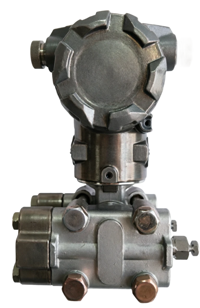
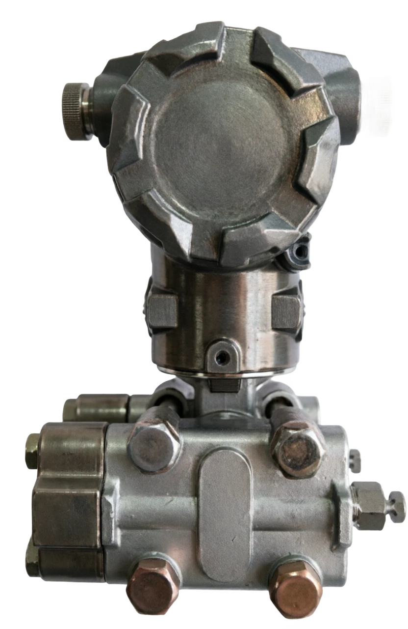
Smart differential transmitter.

(a) Three main technical routes for the differential electromechanical and single-crystal silicular resistance are the dominant industry: (1) the differential (represented in the 3051 series) high and low pressure side pressure is applied to separate sides of the isolated film, which is fed with silicon oil to the central measuring room; (a) The film produces a micro-diverse shift (microscale only) at pressure differentials, changing the amount of the electrical capacity between the film and the fixed polar plate on both sides; The variation in the differential capacity was converted to a telecommunications signal, forming a measurement chain for "pressure differentials to transfer the current of the capacitor." Capable C Relation to film tectonic shiftd: C = ⁇ .A / d ⁇ C/C ⁇ - ⁇ d/d(2) monocrystal silicon-based resistance (MEMS, represented by EJA/silon)
Reference to the smart microvolter classification
Smart differential transmitter . Classification reference diagram

Smart differential transmitter selection support

Provide survey missions, media and installation conditions and obtain product configuration advice.

Contact us
Smart differential transmitter Technical Note

TECHNOLOGY & APPLICATION

Understand the principles, the exact selection.

From measurement principles to field applications, understand the technical characteristics and selection features of smart differential transmitters.

01

TECHNICAL GUIDE

Overview

(Smart Low-Range Differential Pressure Transmitter) is a branch of an ultra-low range in the smart differential transmitter family, which is dedicated to measuring very small differential signals, with a generic range between 0 ~ 50 Pa ~ 0 ~ 40kPa (typical micropressure range is 0 ~ 0.125 ~ 1.5kPa). It converts the small pressure differentials on both sides of the pressure to standard 4-20mA DC (accumulated with a HART digital signal) and access to the DCS/PLC system to achieve remote monitoring and automatic reconciliation.

Compared to conventional smart differential transmitters, the differential transmitter has been specially designed for enhanced sensor film structure, overload protection, zero point stability, etc., as an irreplaceable product of micropressure conditions such as chamber pressure monitoring, clean room pressure control, filter jamming alarms, etc. The first in this series, Smart Pressure Transmitters, the Smart Fragmenter, has introduced conventional range products, which focus on microvoltage specific technologies.

02

MEASUREMENT PRINCIPLE

Operating principle

2.1 Signal transformation chain

There are three main technical routes for differential transmitters, with differential-capable and single-crystal silic pressure resistance being industrially dominant: (1) differential-capacitation (represented by the 3051 series)

High and low pressure side pressure, which acts on both sides of the quarantine film, is passed on to the measurement room centre by the filling of silicon oil (silon chamber);

(a) The film produces a micro-diverse shift (microscale only) at pressure differentials, changing the amount of the electrical capacity between the film and the fixed polar plate on both sides;

The variation in the differential capacity was converted to a telecommunications signal, forming a measurement chain for "pressure differentials to transfer the current of the capacitor."

Measurement formulaClick to see the big picture
C = ε·A / d
ΔC/C ≈ -Δd/d

Capable C in relation to film tablet shiftd: C = ⁇ A / d ⁇ C/C ⁇ d/d(2) monocrystal silic pressure resistance (MEMS, represented by EJA/silicate)

(b) The difference is transmitted through isolated film and silicon oil to single-crystal silic sensitive chips;

(b) The pressure on the silicon film produces a microformation, using semiconductor pressure resistance and changes in the Whistlen bridge resistance integrated on the silicone;

The chip output differential voltage, which is internalized MMU, completes linear correction, temperature compensation, static pressure compensation, output 4~20mA+HART.

(3) Silicon vibrator (high accuracy route)

(a) The pressure differential changes the vibration frequency of the condensed beam and measures the differential pressure by the frequency deviation;

Accuracy up to ±0.035% ~0.1% FS, highly disruptive, suitable for dynamic monitoring.

2.2 Imagination function

Number compensation

(b) An internal temperature sensor (e.g., Pt1000) to compensate for the digitization of temperature drift, non-linear, static pressure error;

HART communication

(a) The application of Bell202 FSK technology to superimpose digital signals on 4~20mA, using hand-held remote assembly, quantation, zero-point calibration, failure diagnosis;

- Stop the nicotine.

Micro-diffusion signals are vulnerable to flow-pulse interference, and the electronic barrier-to-nibration constant can be adjusted for smooth output;

Additional functions

Square root opening output (reduced flow), failure self-diagnosis, sensor health monitoring, multivariant output (discretion + temperature).

03

PRODUCT STRUCTURE

Structure

It's made up of two major components: Survey and Smart Electronics.

Micro-disk special structure design

Super thin-lined amulatory film.

316 L-blank film of approximately 0.05 ~ 0.07 mm thickness, at very low levels to ensure sensitivity under micropressure differentials;

Double-load protective film

Micro-small scale (e.g. 0~125 Pa) corresponds sensors are extremely vulnerable, one-way shocks (e.g., one-sided barrage jams) are highly vulnerable, and both-side protective film is fitted to limit-beams at excess pressure to achieve self-protection;

Temperature isolation design

Low inflationary factor (approximately 0.0005/°C) for symmetric cavity, offset by single side temperature effects;

Optimizing the barometer structure

Some models use a large calibre pressurized cavity or static head/bargeproofing device to reduce the risk of dust plugging (the chamber is under pressure)

Ready.

Survey Department (head)

Composition: high/low pressure side amputated film, silica oil, chamber-composed sensor (or single-crystal silicon chip) functional description: sense micropressure differential and conversion to a single telecommunications number

Overload protection structure

Composition: double-loaded protective film, limit structure Functional description: single side ultrapressurized time-limited bit film to prevent sensor damage

Smart Electronics Department

Composition: 32 bits MMU, D/A conversion, signal-modified circuit functional description: linear, modulated, static, quantification

Show Header

Composition: LCD LCD Header (backlight) Functional description: display of the difference pressure, unit, diagnostic information on site

Communications module

Composition: HART modem (optional RS485-Modbus/FF/PA) Functional description: Communication with handheld, DCS digital

Connector End and Shell

Composition: Aluminium alloy/stainless steel insulation casing functional description: protection (IP65/IP67) and blast protection (Ex d/Ex ia)

Process connection

Composition: 1/4NPT, M20x1.5 pressurized interface, with three valves

04

TECHNICAL GUIDE

Analysis of strengths and weaknesses

4.1 Advantages

Very sensitive.

(a) Small pressure differential changes of 0.1 Pa class, with resolution well above conventional differential transmitters;

High precision and high stability

Standard ±0.075% ~±0.2% FS, Silicon resonance up to ±0.05%; long-term capacitor drift ≤±0.15% / 6 months;

Wide turndown ratio

10:1 ~100:1 free to reduce the range of the field without replacing the instrument;

It's very resistant.

Double-load protective film design, static pressure tolerance up to 16~32 MPa, single-side impact not easily damaged;

Smart Digital Functions

(a) Long-range configuration, self-diagnostication, blockage, square root output, low maintenance cost;

Two-way measurements

(b) ⁇ bi-way range (e.g. ±500 Pa) suitable for the chamber ' s negative/simple double-directional fluctuations;

It's slow, it's repetitive.

Single-crystal silicon integrated without adhesive layers, especially suitable for micropressure differential measurements of dozens to hundreds of Pa.

4.2 Disadvantages

Very small pressure differentials are dropping in precision

< 100Pa ' s very small pressure differential, common single-crystal silicon, less than a dedicated capacity micropressure sensor, with careful selection;

Sensitivity to the pressurization system

Light congestion, condensing, leakage of the barometers cause significant errors and high installation requirements;

The temperature is relatively high.

(a) A magnification of the temperature error ratio of the quarts range and doubling of the temperature impact of the Quantities 3, 9 and 0;

Zero drift requires regular calibration

(b) Temperature mutations and vibrations in the environment cause zero-point drift and require periodic verification;

Higher cost

(b) The price of the differential pressure model is higher than the conventional scale product series;

Dynamic response limited

Capable response time 100-500 ms, not suitable for fast dynamic processes (couption < 150 ms is remediable);

Blockage problem

The dust-containing condition such as the chamber's pressure must be fitted with a block-sampling device, otherwise maintenance is frequent.

05

APPLICATIONS

Application area

The chamber's negative pressure monitoring is the most classic industrial application for the differential transmitter.

The boiler burner room is required to maintain a micro-negative pressure of -50~200Pa, which is overpressed by light-fired smoke, while the excessive leak increases the loss of smoke, and the micro-discretion transmitter monitors and connects the wind engine block to the key instrument for the safe economic operation of the boiler.

Electricity

Typical application: boiler chamber negative pressure monitoring, I/II wind pressure, empty preserver differential, dust scrubber pressure differential range: ±100 Pa~±2kPa

Heating air conditioners (HVAC)

Typical applications: wind pipe static/pressure differential, air conditioning unit filter jamming alarm, wind engine control Quantities range: 0~100Pa~2kPa

Cleaning room/pharmaceuticals

Typical applications: Clean room pressure differential gradient control (5~20 Pa), sterile workshop positive pressure maintenance range: 0~50 Pa~100 Pa

Semiconductor

Typical application: micropressure control of the process cavity, monitoring of the pressure differentials of the cleaner plant Quantities range: 0~50Pa~500Pa

Environmental protection

Typical application: CEMS Frozen Flow Speed Monitoring (Father-Skin-Steved), Ddegrade Dust Control Difference Range: 0~1kPa

Medical

Typical application: respiratory/aesthetic air flow monitoring, negative pressure chamber differentials, range: 0~500Pa

Chemical/ petrochemical

Typical applications: fluidized-bed differential pressure and low-flow differential pressure across a restriction. Measuring range: 0–5 kPa to 0–40 kPa.

Building control.

Typical application: VAV system, pressure-repression system control range: 0~100 Pa~1kPa

Field of testing

Typical applications: valve sealing tests, packaging air-condensing tests, vacuum cavity medical leaks Quantities range: customised according to the work conditions

06

TECHNICAL SPECIFICATIONS

Technical Parameter Table

For reference purposes, the Industrial Universal Smart Fragment transmitter (3051 microvoltaic/single-crystal-silon microvoltage system):

Technical parameter table · Parameter item / Technical indicatorCross-reference
Parameters itemTechnical indicatorsRemarks
Use ObjectGases are dominant (liquid, steam optional)Microbaric conditions are more gas-intensive.
Measurement range0~50Pa to 0~40kPaTypical microvariant pressure slot: 0-0.125 ~1.5kPa
Double-View Range±50 Pa~ ±40kPa OptionalThe chamber has a double-directional pressure.
Accuracy class±0.075% / ±0.1% / ±0.2% FSHigh precision of ±0.05%
Turndown ratio40:1~100:1The scene is free to move.
Long-term stability≤±0.15% FS/ 6 monthsTypical Capability Value
Output signal4~20mA DC + HARToptional RS485-Modbus/FF/PA
Power supply12~45V DC (two-line)Standard 24 V DC, Power ≤3.5 W
Load capacity0~1650 (24V power supply time)Power voltage Related to Power Power
# Still under pressure #16MPa / 25MPa / 32MPaHigh-pressure condition confirmed.
Overload capacityDouble-load protective film, single-sided ultra-pressure self-protection.Micro differential pressure core protection
Temperature effectsZero. ±0.25% / 55℃ ,Consolidated ±0.5% / 55℃Double the small-scale slot error.
Ambient temperature30~85°C (with LCD head - 30~70°C)—
Process medium temperature40~120℃The heat is a long way off.
Ingress protectionIP65 / IP67Optional NeMA 4X
Explosion protection markingEx ia IIC T6 / Ex d IIC T6 GbBen-An/Explosion
Postomas316L (standard), Haq Alloy C, tantalumCorrosion media optional
Fill fluidSilicon oil (standard), oil-free fluorineOxygen condition is disabled.
Process connection1 / 4 NPT, M20 x 1.5, with three valvesPressure-based installation
EMI/RFI Impact20 ~ 1000 MHz, 30 V/m strong <±0.1% scaleAnti-variant frequency interference design
Vibration effects±0.05% URL/g (200 Hz Any Axis)—
Show HeaderLCD with backlight to show differential pressure/percentage/engineer unitZero-point scale adjustment in-situ
07

SELECTION GUIDE

Select Table

7.1 Selected core elements

  1. 01

    Pressure range

    1.5 ~2 times the process-normally pressured margin, with the minimum Quantification Scaling accuracy to be confirmed;

  2. 02

    Silent pressure level

    Confirm the maximum working static pressure ⁇ transmitter static rating of the pipe;

  3. 03

    Precision requirements

    Clean room pressure difference (±1 ~ 2 Pa level control) selects high accuracy electric capacitor; general HVAC selects MEMS pressure resistance;

  4. 04

    Media and Materials

    General gas 316L; corrosive algae/ tantalum; oxygen-selected fluorine filling;

  5. 05

    Dust Work

    The chamber shall be under pressure with a blocker/silent head and be regularly cleaned;

  6. 06

    Explosive protection requirements

    Chemical Area Selection Ex ia/Ex d;

  7. 07

    Mounting accessories

    Triple valves (plating), barp tubes, cut-off valves, gas/excess containers.

7.2 Model Selected Expressions (3051 Microdiscretion Pressure System)

3051 CD - [Quantification Code] - [Exit] - [Map/Line Sewer] - [Procedure Connection] - [Explosion Control] - [Standhead] - [Option]

7.4 Comparison with conventional smart differentials carriers

Select the table . Code bits / OptionsCross-reference
Code bitsOptionsAnnotations
The quantum code.30-0.125 ~1.5 kPa (microvolt pressure)
40-1.25~7.5kPa
50-6~40kPa
Output CodeA4-20mA + HART
MRS485-Modbus
Wetted materialsS316L
HHawthorne Alloy C.
TTantalum
Process connection11/4NPT
2M20×1.5
Fireproof.EEx ia IIC T6
FEx d IIC T6 Gb
NNo blast-proof.
HeaderM5LCD Render light
OptionsB4Triple valves
QBlocked sampling devices
ApplicationsRecommended scaleType of recommended technologyPrecision requirementsAnnex recommendations
Boiler chamber pressure.±200Pa~±2kPaCapable/single-silvigen±0.2%Trivalve group + block-proof sampler
Clean room pressure differential gradient0~50Pa/0~100PaHigh precision electric conceiting± 0.1% or higherFast interface + multiple-road switch valve
HVAC Filter Pressure Difference0~500Pa~2kPaMEMS Pressure±0.5%Straight-coach sampling
Empty preset/disposer differential0~1~2.5kPaCapacitive±0.1%~0.2%Triple valve + blower
Fluid bed pressure differential0~5~40kPaCapable/single-silvigen±0.075%Frank's pressure plus quarantine.
Frozen Flow Speed (CEMS)0~1kPaCapacitive±0.2%Piscilla-Turkage+Closure
Medical/respirator0~500PaMEMS Pressure±0.5%Low cost of energy
Selecting Table . Contrast / Smart Microvolt TransmittersCross-reference
ComparativeSmart differential transmitterGeneral smart differential transmitter
Minimum scale0~50Pa rise0~1kPa Quick (common 0~6kPa)
Maximum Full Range≤40kPaUp to 10~40 MPa (high-pressure type)
- Possibilities.Extremely low (super thin film)Higher
Overload ProtectionDual-side protective film (core design)General One-way Protection
Typical applicationsThe chamber's pressure, the clean room, the filter.Fluorescent, liquid level, density
Anti-prision tube leaking capabilityWeak (micro-signal susceptibility)Stronger.
PriceHigherGeneral
08

TECHNICAL GUIDE

Installation and use points

  1. 01

    Organisation

    (b) Shortening the pressure tube by approaching the pressure point as close as possible; horizontally installed symmetry of the pressure tube on both sides to avoid single-side water column differences;

  2. 02

    Zero shift

    The installation must be followed by zero-point calibration and the two-side pressurized tubes are applied to the atmosphere and then zero;

  3. 03

    Triple valve operation

    (b) When transported, open the balance valve, then the high-pressure side, the low-pressure side, and finally close the balance valve to prevent single-side shocks;

  4. 04

    Blockage maintenance

    (b) The sampling device is regularly blown out of the dust-containing condition (convene pressure on the furnace);

  5. 05

    Temperature isolation

    (b) Use long-spread cavity tube isolation when the temperature of the medium is excessive to avoid errors due to inflating the filling fluid;

  6. 06

    Periodic validation

    The micropressure slot recommended a shorter cycle, as measured by JJG 882 (disk Transmitters check protocol).

09

TECHNICAL GUIDE

Concluding remarks

It is a typical product of process detection in the "small and large" field, where the measured pressure differentials are often just a few dozen Pas, but they support key links such as boiler safety, clean room compliance, and the economic operation of the filter system. The selection should focus on four main elements of the design of the minimum range, overload protection structure, zero point stability and pressurization system; The main maintenance focus in use is blockage, leak control, and regular school zero. With the development of MEMS and smart compensation technologies (Ai temperature-revision, wireless network, SIL2/IECEx certification), the MRT is moving towards higher accuracy, lower cost, easier network formation, and applications in new and emerging areas such as cleaners, semiconductors, and medical care are expanding.

References

GB/T 34036-2017 General Technical Conditions for Smart Transmitters, JJG 882 Pressure Transmitters Inspection Procedures, IEC 61508, Instrument Processors Technical Information (3051/EJA series, etc.)