PRODUCT TECHNOLOGY

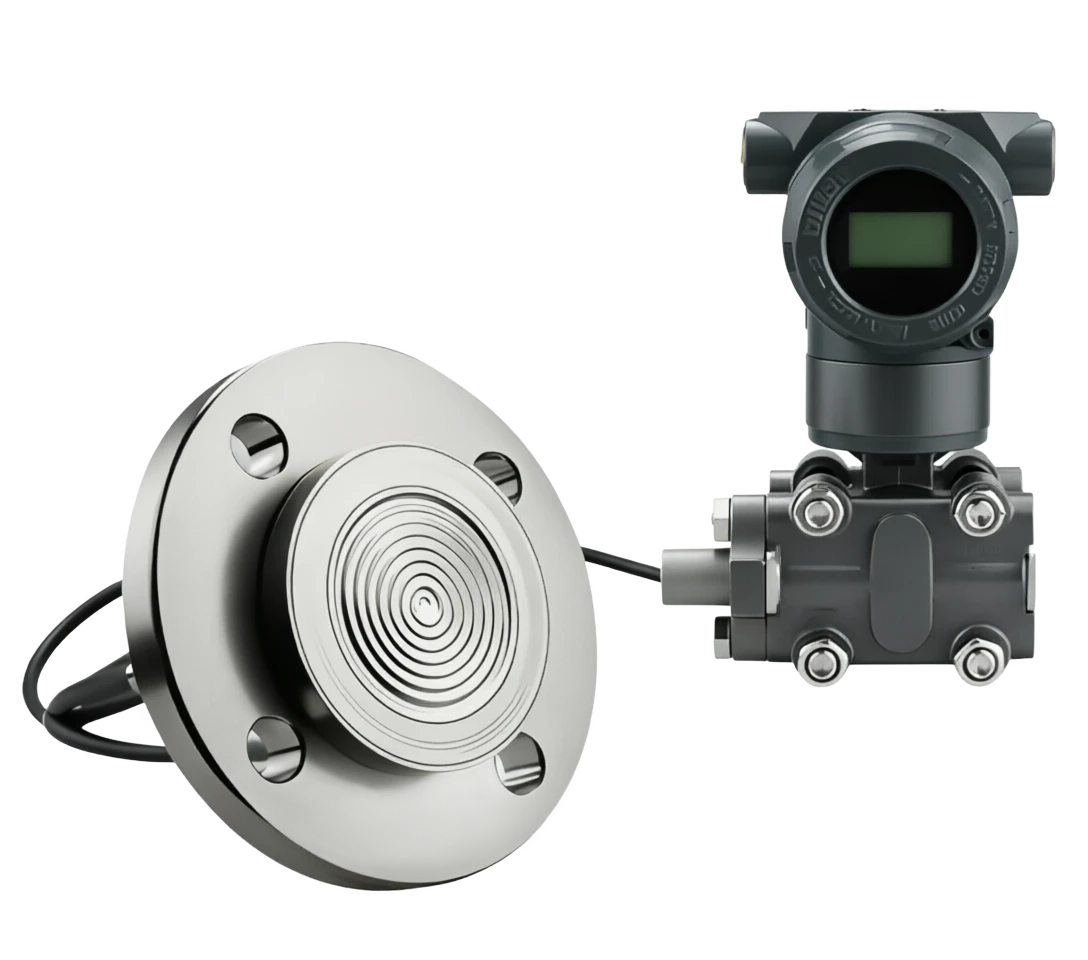
Mono-French diaphragm pressure transducer

Operating principle

The mono-French diaphragm pressure transducer.

Work based on mature monolithic silicular resistance or the principle of acoustic sensory. The measured medium pressure, after having functioned in an isolated film, is transmitted to a high-precision single-crystal silic sensitive element through internal filling fluids (usually medical-grade silicate oil). A sensitive element undergoes a minor transformation at pressure, resulting in a minor change in its internal resistance or the capacity of the element in relation to the linearity of the pressure. This weak telecommunications code was converted into a standard industrial signal (usually 4-20 MA current signals, which can be superimposed with HART communication protocols) proportional to the measured pressure, after magnified, temperature compensation and non-linear correction by the dedicated ASC-magnification circuit.

  1. 01

    1 The detected medium provides a primary pressure signal

  2. 02

    2 Separating film • Contacting media to convert pressure to mechanical transfer

  3. 03

    3 Filling fluids . Transfer pressure to sensitive components while separating media

  4. 04

    4. Sensitive elements . Conversion of pressure to resistance/capacitation change

Support for the Mono-French diaphragm pressure transmitter selection

Provide survey missions, media and installation conditions and obtain product configuration advice.

Contact us
· Technical Note

TECHNOLOGY & APPLICATION

Understand the principles, the exact selection.

From measurement principles to field applications, the technical features and selection features of mono-French diaphragm pressure transmitters are understood.

01

TECHNICAL GUIDE

Overview

It is one of the key instruments in the industrial process measurement and control system, which is used to measure pressure signals for liquids, gases or vapour media and is installed directly on the pipe or container through the French.

This product transmits the pressure of the process medium to internal sensitive elements through metal separators at the French end, which are used to provide reliable transmission of pressure signals with special filling fluids. Its integrated design will save the installation of traditional barbed wires and associated valves, significantly reduce system costs and increase the speed of measurement response, especially in the case of conventional pressure carriers such as viscous, crystallized, condensable, corrosive and particulate-containing materials.

This technical summary will be structured in terms of the rationale, structure, strengths and weaknesses, application areas, technical parameters and selection guides, and will provide a reference basis for engineering design, equipment selection and on-site maintenance.

02

MEASUREMENT PRINCIPLE

Operating principle

2.1 Core sensory principles

Work based on mature monolithic silicular resistance or the principle of acoustic sensory. The measured medium pressure, after having functioned in an isolated film, is transmitted to a high-precision single-crystal silic sensitive element through internal filling fluids (usually medical-grade silicate oil). A sensitive element undergoes a minor transformation at pressure, resulting in a minor change in its internal resistance or the capacity of the element in relation to the linearity of the pressure.

This weak telecommunications code was converted into a standard industrial signal (usually 4-20 MA current signals, which can be superimposed with HART communication protocols) proportional to the measured pressure, after magnified, temperature compensation and non-linear correction by the dedicated ASC-magnification circuit.

2.2 Pressure transfer pathways

Motion of work . Serial number / chainCross-reference
Serial numberLinkFunctional description
1Media testedProvides raw pressure signals
2Isolation diaphragmContact medium, convert pressure to mechanical transfer
3Filling fluidTransfer pressure to sensitive components while separating the medium
4Sensitive shapesConvert pressure to resistance/capacitation change
5Zoom in on the circuits.Signal amplification, temperature compensation, linearization
6Output signal4-20 MA + HART standard industrial signal
03

PRODUCT STRUCTURE

Product structure

3.1 Structure

Composed of process connective, measurement quarantine, signal processing and shell structure, typical knots

The components are as follows:

Page 3

3.2 Typical structural diagram (text description)

Bottom to Top

Process Franc (1) ⁇ Separating film (2) ⁇ Filling fluid cavity (3) ⁇ Sensitivity Component cavity (4) ⁇ Magnifying circuit board (5) ⁇ Switchend (6) ⁇ Shellcaping (7).

The French end is the part of the detected medium that is directly exposed, while the sensitive element cavity is completely sealed in the shell, and physically isolated from the electronic component by filling fluids connected to the film.

Page 4

Process Frank.

Consisting with pipes or containers, subjecting to medium pressure 316L / Hapsy Alloy C-276

Isolation diaphragm

Directly sense pressure, and filling fluids into sealing systems 316L / Haps alloy C / tantalum / monal

Filling fluid

Pass pressure, quarantine medium, provide temperature compensation Silicon oil (conventional / high / low temperature)

Sensitive shapes

Convert pressure to telecommunications, single-crystal silicon pressure resistance / single-crystal silicon capacitor

Zoom in on the circuits.

Signal regulation, linearization, temperature compensation ASIC integrated circuit

Shell

Protection of internal components, provision of electrical interface Aluminium alloy / stainless steel (IP65/IP67)

Show Header

Show measurements and diagnostics on site LCD (optional backlight)

Connector End

Power and signal output interface Gold plating / Springing

04

TECHNICAL GUIDE

Analysis of strengths and weaknesses

4.1 Main advantages

Direct French-Angled, and the knots can be straight-on.

Specific: Plumbs or containers without pressure tubes, valves and fittings, materials and construction

Persistence-resistant amulatory film force is available.

Specific: Precious metal materials such as Haq alloy, tantalum, monal, for strong corrosive media such as acid, alkali, etc.

The medium is particularly adaptable.

Specific: media for viscosity, crystallity, condensation, particulate matter, effective in avoiding barbed-down piping

Use single for high accuracy measurements

Specific: Crystal Silicon Sensitive Component, typical precision of ±0.075% / ± 0.1%, long-term stability better than 0.1%

Respond fast.

Specific: Integrated structures are lagging without a baroque, and dynamic response times are better than traditional pressure-based transmitters.

The maintenance of small motion parts is not limited to the following:

Specific: no-charged leak point, high reliability, average no-failure working time (MTBF) of up to 10

Support for the communication.

Specific: live bus lines such as shaRT, FOUNDATION Fieldbus, PROFIBUS-PA, easy

Security level high

Specific: Exia IIC T6 / Exd IIC T6 blast-proof level, applicable to hazardous sites.

Disadvantages and use restrictions

Temperatures affect relative membranes larger and larger than fill

Response response measures recommended: Filling is subject to temperature and high temperature conditions require the choice of high temperature filling fluids, with a condenser or, if necessary, with a condenser or

Installation position requires high level

Response response proposal: installation or side-loading with attention to flannel stress, and inappropriate installation can cause zero drift or mismeasurement

Higher one-time investment unit cost

Response proposal: higher than normal pressure transmitters, but combined with cost savings for the barbed wire, overall engineering costs

Irreparable separation of film damage

Response response recommendation: Once a film has been distorted by mechanical shocks or a crystal squeeze of the medium, the overall process needs to be replaced by the Francs

Relatively complex maintenance

Response recommendations: On-site maintenance requires depression, cleaning, decomposing of flanges, and longer time for relatively pressurized structural repairs.

The French mark is subject to multiple standards.

Response response proposal: Select different French standards and seal face forms such as ANSI, JIS, DAN, GG/T (RF / )

05

APPLICATIONS

Application area

The mono-French diaphragm pressure transducer has been widely used in the following industries, with the following characteristics: p. 5, p. 6

Reacting pyrochlor, chemical evaporation towers, storage

Typical application scenario: pressure measurements of tanks, pipes and catalyst plasma pipes, especially for high polyesters, PVCs, alkyl, etc.

wellheads, oil and gas fields,

Typical application scenarios: water wells, separators, crude oil tank pressure monitoring; applied to a variety of complex issues such as sand, wax, water, etc.

Electricity

Typical application scenarios: boiler packs, pumps, condensed water systems, ashle pipeline pressure monitoring.

Metal and metal

Typical application scenarios: furnace roofs, co-crop-drain, gas pipelines, pressure measurements for the dedustor system.

Paper industry

Typical application scenarios: steam cookers, slurry cleaners, white water recycling, liquid pressure measurements of the slurry pool.

Pharmaceuticals and anti-food products

Typical application scenarios: yeast, CIP washing system, dairy tank pressure monitoring; sanitary level (Tri-Clamp)

Environmental protection of water treatment

Typical application scenarios: entry pumping stations, filters, pharmacological systems, sludge pipe pressure monitoring.

Chemical new materials

PUR, adhesive, coating, dye, high-column pipe pressure measurements.

Seamen on ships

Fuel systems, desalination units, ballast water system pressure monitoring.

06

TECHNICAL SPECIFICATIONS

Technical Parameter Table

The following parameters are generic technical indicators for typical mono-French diaphragm pressure transmitters, and the actual product parameters are based on the plant-out-of-plant data sheet.

Page 7

Technical parameter table · Parameter item / Specification parameterCross-reference
Parameters itemSpecification parametersRemarks
Measurement range0–6 kPa ~ 0–40 MPaOptional overwhelms pressure, surface pressure, negative pressure
Accuracy class±0.075%FS / ±0.1%FS / ±0.2%FSInclude linear, reversible, repetitive
Long-term stability± 0.1% FS/ yearSmarter than 0.1% / 5 years
Output signal4-20 MA + HART (biline)Optional FF / PROFIBUS-PA
Electricity voltage10.5–45 V DC (Standard Type)Benz 10.5-30 V DC
Load capacity0 – 600 times (HART Communications ≥ 250 times)It depends on the power voltage.
Process medium temperature40 °C ~ + 150 °C (conventional silicon oil)High temperature of up to +400 °C (cooled condensers)
Ambient temperature40 ℃ ~ +85 ℃Show the header -20 °C ~ +70 °C
Environmental humidity5% ~ 95% RHNo condensation
Ingress protectionIP65 / IP67Optional IP68
Explosion protection markingExia ⅡC T6 Ga / Exd ⅡC T6 GbBased on GB/T 3836
Electrical connectionM20×1.5 / 1/2 NPTYou can choose the one that's gonna blow up.
Process Connection DN50/ NN80 / NN100 (HG/T / ANSI / JIS /DIN) Customised Special Specifications
Seal face formRF(Stand)/ FF(Stand)/ RTJ(Closed)Based on process needs
Isolation diaphragm material316L / Hapsy Alloy C-276/ tantalum/ monal/ titaniumBased on the medium corrosiveness
Filling fluidSilicon oil (conventional) / HT Silicon oil / fluorine / vegetable oilFood Level Optional FDA Certification
Response time≤ 100 ms. (Standing Nico 0 – 60 s)Electrical blocker
WeightAbout 4.5-8.5 kg (excluding fran)Changed with Frank's specification
Body materialAluminium alloy (spray)/ stainless steel 316LPreservative grade options
Communications agreementsHART 7 / WirelessHART / FF / PROFIBUS-PAOptional Smart Diagnosis
07

SELECTION GUIDE

Select Table

This section provides an optional reference for the dimensions of "quantitative specifications" and "appliance scenarios" to facilitate rapid positioning models by engineers during the design phase of the project.

7.1 Selecting the format by Quantification Specification

7.2. Select the format by application

7.3 Common French specification checklists

Page 8, page 9

Selective Table · Quantification Code / Measurement RangeCross-reference
The quantum code.Measurement rangeTypical applicationsRecommended film material
RC-010-6 ~ 40 kPa microPressure measurement, tank fluid level (low density medium)) 316L
RC-020–40 ~ 200 kPaPressure containers, liquid level measurements316L
RC-030–0.2 ~ 1 MPaVapour, low pressure pipe316L / Hax C
RC-040–1 ~ 4 MPaGeneral process conduits, response pads316L / Hax C
RC-050–4 ~ 10 MPaHigh pressure steam, water injection system316L / Hax C
RC-060–10 ~ 40 MPaSuper-high pressure process, acoustic systemHQ C-276/Ni-Blutonium
RC-V100 ~ 0 kPa / ±100 kPaVacuum and negative pressure measurements316L
RC-A0-40 kPa ~ 2 MPa (insulation)Sealed container, pressure out.316L / Hax C
ApplicationsMedia FeaturesSuggested selection elements
Vapour / High TemperatureT > 150 ℃Cooled condensers / Select high temperature silicon oil / high temperature film
Sticky / Flex-Cordable MediumPolymer, slurry, honey.Hemphland (inline film)/ Large caliber French
Corrosive mediaAcid, alkalis, strong oxidesHAB C-276/ tantalum film + PTFE liner
Food / Pharmaceutical industryHealth requirementsSanitary Tri-Clamp Frank / FDA Silicon
Flammable explosive sitesGas fields, chemical installationsExia or Exd blast-proofing / IP67
Low / MicropressureLow pressure, high sensitivity.Select low-quantification specifications / raise accuracy
HF Dynamic MeasurementPulse pressure.Shorten response time / Reduce blocker settings
High viscosity slurryCatalysts, pulp, oily mud.Insert French / Large-sized film
Ocean/ Salt Mist EnvironmentCl, wet hot.316L shell / coating upgrade / IP68
Specification DesignatorNominal pipe sizeNominal pressureSeal face form
F-50ADN50 (2")PN16 / 150 lbRF (Darling)
F-80ADN80 (3")PN16 / 150 lbRF (Darling)
F-100ADN100 (4")PN16 / 150 lbRF (Darling)
Selective Table . F-50H / DN50Cross-reference
F-50HDN50PN40 / 300 lbRF / RTJ
F-80HDN80PN40 / 300 lbRF / RTJ
F-50CDN50PN100 / 600 lbRTJ
F-Tri50DN50 (2")Health levelTri-Clamp, fast-load.
F-Tri80DN80 (3")Health levelTri-Clamp, fast-load.
08

SELECTION GUIDE

Selection of guidance and attention

8.1 Selective Steps

8.2 Installation and use of attention

  1. 01

    The sealed face shall be inspected prior to installation and the mats shall be of the same type as the design.

  2. 02

    The tight bolts shall be cross, symmetrical and evenly increased to avoid single-sided receptors leading to film distortion.

  3. 03

    The installation should be located far from the vibration source, the electromagnetic interference source and, if necessary, the devibrancy support frame.

  4. 04

    When the medium temperature is above 85 °C, it is proposed to add a condenser/condenser between the extraction vent and the carrier.

  5. 05

    When measuring steam or other hot media, first vent the condensate pot to avoid a pressure shock on one diaphragm.

  6. 06

    Direct contact with the surface of the isolated film with hard matter (e.g. wrench, steel brush) is strictly prohibited.

  7. 07

    The shipment should be preceded by a zero and full-scale validation and the HART handheld may be re-tested.

  8. 08

    Periodically check the integrity of the shell seal, the Gran Head, and the cable shield.

  9. 09

    The installation of hazardous sites must meet the requirements of the blast-proof level for the wiring and location.

  10. 10

    The power should be cut off for long periods of time, the pressure valves closed and, if necessary, the shield caps fitted.

8.3 Maintenance and troubleshooting

Page 10 - End of Document -

Selected guidance and attention . Steps / Key elementsCross-reference
StepsKey elements
Step 1 . Clearly measure objectsConfirms the name of the detected medium, temperature, pressure range, corrosivity, viscosity, particle or crystallity.
Step 2 . Determination of the scaleSelect the appropriate scale according to the maximum working pressure, which should be the normal working pressure 1 / 3 ~ 2 / 3 Between.
Step 3 Selecting film materialBased on the corrosive properties of the medium, the selection of materials such as 316 L, HS C-276, tantalum, Monnar, etc.
Step 4 . Select FillingSelect conventional silicon oil, high temperature silicon oil or fluorine based on the temperature of the medium.
Step 5 Selecting the French specificationSelecting the French standard, the public pressure, the sealed face form based on the calibre of the pipe and the process pressure.
Step 6 . Confirm output signalSelect 4-20 maA + HART or FF/ PROFIBUS-PA bus protocol.
Step 7 Safety and protectionThe blast and protection levels are selected according to the hazard area on site.
Step 8 Communication and diagnosisAssess whether intelligent diagnostics, remote marking, etc. are required.
Selection guidelines and attention · Common failures / Possible causesCross-reference
Common malfunctionsPossible causeSuggested measures
Output constant 4 maA or 20 maAPower supply abnormal / connection opening / film fractureCheck the power voltage, turnbacks, film.
Output values are not consistent with pressureProcess setting error / zero point drift / medium temperature shadowRemark zero points and quarts, check the filling fluid.
Zero points are drifting badly.Installation stress / temperature change / film impactRe-commencing Frank. Checking for ambient temperature.
Communication Failed (HART)Loaded electrical resistance < 250 / interference / protocol versionCheck load resistance, use shield cables.
Show anomalies/ noneHeader failure/ power supply is inadequateCheck LCD module and power supply