PRODUCT TECHNOLOGY

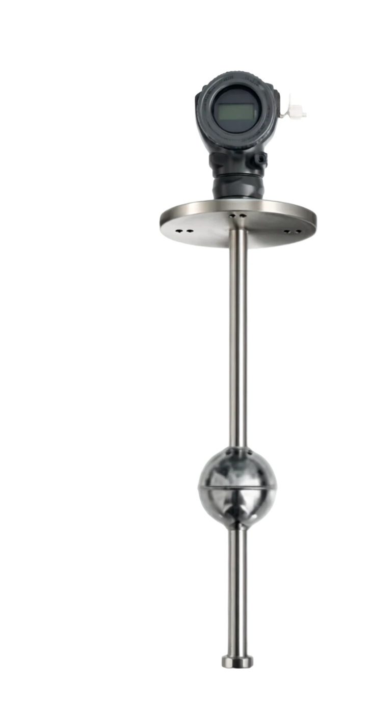
Magnetic stretcher bitometers

Operating principle

Magnetic stretching fluids.

Magnetostic Effect is the microcrystalmic aberration of the magnetokinetic material, which results in macro-formation of the material, as it is performed in the external magnetic field. If a transient current magnetic field were to be superseded on the magneticly deciphered iron, the speed of the two magnetic fields, which are spreading at a local level, is extremely small, and is an ideal time flight measurement medium. The core of the measuring pole is a nickel-based alloy magnetic stretching wave conductor, pre-magnetic along the axis. The float (inline permanent magnet) slides along the outer wall of the wavemap, and the magnetic field at the float position interacts with the magnetic direction of the wavemagnetic tube. The circuits exert transient low current pulses at the end of the wave pipe, and the circular magnetic field from which the current meets the floating magnetic field, producing a reversal wave (local crystal reversal) at short notice. Turn the wave along the tube.

  1. 01

    Distance of float to top sensor L = v t, where v is to reverse wave speed (about 2800)

  2. 02

    Single floats: measure liquid level height;

  3. 03

    Double plume: simultaneous measurement of the fluid level and oil interface (oil water separators, storage tanks interface); p. 3

  4. 04

    Multi-float: can measure the position of 1 ~5 liquids/ interfaces simultaneously;

Magnetic stretching fluids selection support

Provide survey missions, media and installation conditions and obtain product configuration advice.

Contact us
Magnetic stretching fluids . Technical note

TECHNOLOGY & APPLICATION

Understand the principles, the exact selection.

From measurement principles to field applications, the technical characteristics and selection elements of the Magnetic Scalculation Plotometer are understood.

01

TECHNICAL GUIDE

Overview

(Magnetosticic Level Transmitter, also known as Magnetic Extremistration Portfolio Sensor, Magnetic Eflex Lampometer) is a high-precision liquid/interface gauge based on magnetic stretching (Weideman Effect/WiedemannEffect) and time flight (Time-of-Flight) principles. It is embedded in the measuring pole with a magnetic stretching wave conductor, which accurately determines the height of the float by measuring the time of reversal wave transfer triggered by the position of the float, and can be measured at ±0.5 mm, with a higher resolution than 0.1 mm.

The magnetometric elasticity is the dominant choice in high-end liquid position measurement such as high resolution, high stability, high repetition and simultaneous measurement of liquid level+interface+ temperature multivariant. It can be used as a separate liquid-placer or as a remote-ranger in conjunction with magnetic roller-board-level-meters, achieving the dual output of "field vision + far-off 4-20 MA + HART".

This document will provide a systematic elaboration of the rationale, structure composition, comparison of strengths and weaknesses, application areas, technical parameters and selection guides, which will provide a reference for engineering design, equipment selection and on-site maintenance.

02

MEASUREMENT PRINCIPLE

Operating principle

2.1 Magnetic scalability effect

Magnetostic Effect is the microcrystalmic aberration of the magnetokinetic material, which results in macro-formation of the material, as it is performed in the external magnetic field. If a transient current magnetic field were to be superseded on the magneticly deciphered iron, the speed of the two magnetic fields, which are spreading at a local level, is extremely small, and is an ideal time flight measurement medium.

2.2 Time flight measurement principles

The core of the measuring pole is a nickel-based alloy magnetic stretching wave conductor, pre-magnetic along the axis. The float (inline permanent magnet) slides along the outer wall of the wavemap, and the magnetic field at the float position interacts with the magnetic direction of the wavemagnetic tube. The circuits exert transient low current pulses at the end of the wave pipe, and the circular magnetic field from which the current meets the floating magnetic field, producing a reversal wave (local crystal reversal) at short notice.

Turning the wave along the wave pipe in two directions.

One end of the wave catheter returns to the top to detect the sensor, is detected by the voltage/magnetic sensor, recording the time between pulse discharge and reversal of the wave return t;

  1. 01

    Distance of float to top sensor L = v t, where v is to reverse wave speed (about 2800)

m/s) is compensated in real time by the temperature sensor measured for the temperature of the wave-cylinder.

2.3 Multivariate Measurement

The greatest advantage is to support multi-float + temperature multi-variate measurements

  1. 01

    Single Float

    (b) Measurement of liquid level height;

  2. 02

    Double Float

    Simultaneously measure the fluid level and oil and water interface (oil and water separators, storage tanks interface); p. 3

  3. 03

    - It's a bit of a plume.

    1 ~ 5 liquid/ interface position can be measured simultaneously;

  4. 04

    Temperature sensors

    Integration of Pt100 / Pt1000 temperature elements at top / bottom of wave pipe, output of average medium temperature or top /

The temperature at the bottom is poor.

2.4 Signal transmission pathways

Page 4

  1. 01

    The interaction creates a mechanical reversal wave along the axis of materials. The reverse wave is about to be in the wave pipe.

  2. 02

    Effect 2800

  3. 03

    / m/s

Motion of work . Serial number / chainCross-reference
Serial numberLinkFunctional description
1Tested packagingsProvide original liquid / interface signal
2Measurement rod protection tubeProtect the wave pipe and floats.
3Float (with magnet steel)Follow liquid surface or interface
4Pulse circuits.Generate pulse currents in the wave catheters.
5Magnetic stretch waveming conduitsAnd it's a reverse wave and a transient.
6Turn-off detector.Voltage / Magnetic Sensor detected the return signal
7Time measurement and temperature compensationConvert floats to top distance
8ASIC / MicroprocessorSignal processing, convert to liquid / interface value
9Output signal4–20 mA + HART / FF / PROFIBUS-PA
03

PRODUCT STRUCTURE

Product structure

3.1 Typical structural composition

It consists of four basic components of measuring rod components, floats, signal processing units, process connections and shell.

The structural components are as follows:

3.2 Typical structural diagram (text description)

Connect Box(s) 9 Show the header ( ) 10 ) Microprocessor ( ) 7 ) ⁇ Reversal Wave detector 4 Magnetic extruding wave tubes () 2 )

⁇ Float 2 (interface, 3) Plateau 1 (liquid, 3) pulsed circuit (5).

Of these, Plumber 1 measures the surface height, Plumber 2 measures the location of the oil and water interface, and Temperature Sensors (6) measures the real-time temperature of the wave pipe for reimbursement.

3.3 Structure Classification

Page 5, page 6

Measurement pole (probet)

Main function: Carrying wave catheters and floats and supporting the insertion of container 31 Usual material/ specification: 6L / 304 / Hapsy alloy / titanium / PTFE line

Magnetic stretch waveming conduits

Main function: Generate and transmit the reverse wave (core component) Usual material / Specification: Nickel-based alloy / Iron-based non-crystal alloy

Float (1-5)

Main function: Move with liquid / interface, with an inline constant magnetic 31 body 6L / common material/ specification: HSD / titanium / PTFE (inline N35-N52)

Turn-off detector.

Main function: Check out the reverse wave of return and convert it to telecommunications. Common material / Specification: voltage ceramic / Magnetic sensors

Pulse circuits.

Main function: Generate pulse currents in wave catheters Common material / Specification: Special ASIC / FPGA

Temperature sensors

Main function: Measurement of wave-conductor temperature for temperature compensation Usual material / Specification: Pt100 / Pt1000

Microprocessor / EEPROM

Main function: signal processing, parameter storage Usual material / Specification: MMU + EEPROM / Iron electric storage

Process connection

Main function: Connect to container or top Frank D Usual material / Specification: N50 / / NN80 Frank / 1/2 NPT / G

Switchbox / Connector End

Main function: Power and signal output interface Common material / Specification: Aluminium alloy / stainless steel / IP65/IP67

Show Header (optional)

Main function: Show liquid position/ interface / temperature commonly used materials / specification: LCD (opposable backlight)

By installation

Type: Top (most commonly used) Characteristics: insert measuring poles from top of the container and occupy top space

Type: Side-packaging Description: Measurement of bending or soft-bar structure through side-frand connectivity

Type: external (magnetic coupling) characterization: measuring poles attached to the outer wall of the container without openings

By float

Type: Single floater

Type: Double-float Description: measure the liquid level at the same time + interface (e.g. oil and water interface)

Type: Multi-float Description: Measuring multiple interfaces (e.g., stratification media)

Measured variables

Type: Single variable type characterization: output fluid / interface signal only

Type: Multivariant Type characterization: also output liquid level + interface + temperature

By Output Protocol

Double-linear 4-20 MA + HART is the most common system integration

FF / PROFIBUS-PA Field bus type for advanced diagnosis

04

TECHNICAL GUIDE

Analysis of strengths and weaknesses

4.1 Main advantages

Extremely measured accuracy

Specification: Typical precision ± 0.5 mm/ ± 1 mm is the highest level of medium precision in the industrial liquid-bitometer.

Super-high resolution, available.

Specific: 0.1 mm, which allows for the identification of very small fluid-level fluctuations, applicable to the measurement of trade in tanks and precision process control

Excellency of repetition

Specific: Repeated error usually ± 0.05 mm, with long-term stability better than ± 0.5 mm/year.

Multiple variables measure simultaneously

Specific: Single instrument can simultaneously output liquid levels, interfaces, temperature multiplex signals, with high value for money.

Non-contact measurement core

Specific: There is no mechanical friction between the float and the measuring pole, resistant to wear and tear, long life.

Strong against electromagnetic interference.

Specific: Reversing the wave to mechanical wave, immunizing electromagnetic interference, applicable in high-power electric settings.

Temperature Auto fixes

Specific: The temperature of the wavemap is measured in real time by the built-in temperature sensor and the temperature is compensated for the reversal of the wave speed.

Support for remote diagnosis H

Specific: ART 7 / FF / PROFIBUS-PA bus, remote query instrument status, temperature, liquid position

Flexible installation

Specific: Various modes of top, side, and external fit can be used to fit the various types of field conditions.

Disadvantages and use restrictions

It's relatively high, magneticly shrunk.

Response response proposal: wave catheters + high time measurement circuit costs, total machine prices about 3 of the magnetic roller tablets

Not applicable to sticky, crystal-friendly media

Response response recommendation: Floats may be packaged, carded or clogged, resulting in unmeasureable.

Not applicable to solid particles mediums containing large quantities

Response response proposal: particulate matter is easily contained in the gap between float and protective tube, resulting in a card delay.

Media density adaptation

Proposal for response measures: Face measurement requires two medium density differentials ≥ 0.05 g/ cm³, which are difficult to discern.

The medium temperature limit is limited

Response response measures recommended: The working temperature of the conventional waveming tube ≤ 125 ℃, which requires special design or protection at high temperatures.

Complex maintenance

Response response recommended that the failure of the wave conduit and floats require overall re-establishment and on-site replacement difficulties.

Vertically Installed

Response measures recommend that measuring poles must be vertical and tilting can cause reversal wave oscillation or loss of float cards.

High space requirements for installation

Response response proposal: The top-loading requires the insertion of space at the top of the container, and the larger the range, the greater the space requirement.

EMC high protection requirements

Response measures recommend that high voltage pulses firing circuits be shielded by EMC to avoid interference with surrounding instruments.

05

APPLICATIONS

Application area

The magnetometric elastication platitudes are used extensively for the following high-end liquid levels / interface measurements with high accuracy and multivariability capabilities: Page 7, page 8

Measurement of oil trade

Typical application scenario: Trade measurement of oil / finished oil storage tanks, measurement accuracy requirement ± 1 mm, meeting OIML / API standards

LNG / Liquefied Gas Refuelling

Typical application scenario: LNG Ball Cans, LUD Tanks (deep cool - 196 °C).

Gas fields

Typical application scenarios: crude oil separators, sink tanks, EDU interfaces and fluid levels, water-injecting gas well flow monitoring.

Petroleum chemicals

Reaction, polymer, catalyst-slurry fluid + interface measurements.

Oilwater separators

Oil - water interface, alkali - oil interface, oil - acid emulsion interface measurement.

Electricity

Boiler pack water level (±1 mm accuracy), HLP heater fluid level measurement.

Paper industry

Black cells, steam boilers, white water recovery systems, liquid slots/ interfaces.

Pharmaceuticals and food

Fermentation cans, CIP Return tanks, sanitary fluid level (FDA / 3A certification).

Environmental protection of water treatment

Screeching ponds, sediment pools, liquid-level measurements (self-control systems).

Laboratory and metrology tests

Standard liquid-bit devices, calibration/ calibration device packages.

06

TECHNICAL SPECIFICATIONS

Technical Parameter Table

The following parameters are generic technical indicators of typical magnetic elasticity (MAL)-levels, and the actual product parameters are based on the plant-output data sheet.

Page 9

Technical parameter table · Parameter item / Specification parameterCross-reference
Parameters itemSpecification parametersRemarks
Measuring VariablesLiquid / Interface / Temperature (Multivariate)Support for 1 ~ 5 floats
Measuring span200 ~ 6000 mm (standard)It can reach 12,000 mm, maximum 20,000.
Measurement accuracy± 0.5 mm (standard) / ± 1 mm (high range)High-end model up to ±0.25 mm
Resolution0.1 mm (standard)High end 0.025 mm
Repeatability±0.05 mmGuarantee ± 0.1 mm
Long-term stability± 0.5 mm/ yearBetter than ±0.2% FS/ year
Temperature measure range40 ~ +125 °C (inline temperature sensors)Differentiated based on model
Temperature measure accuracy±0.5 ℃ / ±1 ℃Pt100 / Pt1000 Level
Medium density≥ 0.40 g/ cm³ (Line Plasma)Interface Floating Condensity Disconnection ≥ 0.05 g/cm³
Operating pressure0-1.0 MPa (General)/ 0-4.0 MPa/ 0-10 MPaHigher stress will have to be customised.
Process medium temperature40 ~ +125 °C (general)High temperature +200 °C/ Low temperature - 196 °C
Ambient temperature40 ~ +85 ℃Show watch header -20 ~ +70 °C
Environmental humidity5% ~ 95% RHNo condensation
Ingress protectionIP65 / IP67 / IP68IP68 for prolonged underwater settings
Explosion protection markingExia ⅡC T6 Ga / Exd ⅡC T6 GbBased on GB/T 3836
Electrical connectionM20×1.5 / 1/2 NPTYou can choose the one that's gonna blow up.
Process connectionPN50 / PN80 Frank / 1 NPT/ G1Customised Special Specifications
Output signal4-20 MA + HART 7 (two-line)Multiple variables supersume multiple paths HART
Response time≤ 100 ms (typical)Partially tuned 0~60 s
Measurement of rod material316L / 304 / Hapsy Alloy / titanium / PTFE linerBased on the medium corrosiveness
Float material316L / Harsh / titanium / PTFE / PPCustomise by medium density
Body materialAluminium alloy (spray)/ stainless steel 316LPreservative grade options
Communications agreementsHART 7 / WirelessHART / FF / PROFIBUS-PAOptional Smart Diagnosis
AuthenticationCE / ATEX / IECEx / NEPSI / CCCSelect the CMC / OIML authentication option
07

SELECTION GUIDE

Select Table

This section provides an option reference for five dimensions of "quantitative specification", "measurement variables", "application scenario", "work temperature", "process connection" and quick positioning models for engineers.

7.1 Selecting the format by Quantification Specification

7.2 Table of Type by Measure Variable

Typical application of variable code measurements

7.3 Table of type by working temperature

7.4 Table of types by application

Measurement requirements for oil trade ±0.5 mm , CMC / OIML Authentication MV-IT+ RC-03 + Double Float + Measurement of certified oil-water separation interface oil-water density differential 0.1 – 0.3 g/cm³MV-I+ RC-02 +Dubloons+sanitary LNG/Line ammonia storage tanks deep cold -196℃ TC-L+Austrous stainless steel + special cryogenic sealed 10 Page

7.5 Process Connection Form Spacing

Page 11

  1. 01

    Temperature Code TC-N TC-M TC-H TC-L

  2. 02

    Media temperature -40 ~ +80℃ -40 ~ +125℃ -40 ~ +200℃ -196 ~ +80℃

  3. 03

    Typical applications: constant water, oil tanks, hot oil, medium temperature media, high temperature media (special design) LNG, liquid ammonia, etc., deep cold media

Selective table · The quantum code / range of the rangeCross-reference
The quantum code.Measuring spanTypical applicationsRecommended precision
RC-01200 ~ 1000 mmSmall tanks, buffer tanks±0.5 mm
RC-021000 ~ 3000 mmGeneral reaction, tanks±0.5 mm
RC-033000 ~ 6000 mmMedium vertical tank±1 mm
RC-046000 ~ 12000 mmLarge storage tanks±1 mm
RC-0512000 ~ 20000 mmLarge canisters, towers±1 mm
Variable CodeMeasuring VariablesTypical applications
MV-LLiquid bit (single variable)General liquid level measurement
MV-ILiquid + Interface (double variables)Oil and water interface, oil-alkali interface
MV-TLiquid + Temperature (double variables)The liquid level that needs temperature compensation.
MV-IT liquidBit + Interface + Temperature (three variables)) Measurement of trade in tanks
MV-MMultiple Variables (≥ 3)Layer media, multi-part interface
Temperature CodeProcess medium temperatureTypical applications
TC-N40 ~ +80 ℃Temperature water, oil tanks
TC-M40 ~ +125 ℃Hot oil, medium temperature medium
TC-H40 ~ +200 ℃High temperature medium (special design)
TC-L196 ~ +80 ℃LNG, LSD, deep cold medium
ApplicationsMedia FeaturesSuggested selection elements
Measurement requirements for oil trade±0.5 mm、CMC / OIMLAuthenticate MV-IT + RC-03 + Double Float + Measurement Authentication
Oil-water separation interfaceOil - Water density difference 0.1 – 0.3 g/cm³ MV-I + RC-02 + Double Float + Health
LNG / LSD tankDeep cold - 196 °CTC-L+OZ +Special cryogenic seal
Selective table · Responsive & Precision Control / Corrosive, High TemperatureCross-reference
Precision control of reactionCorrosive, high temperature.RC-02 + HSD / titanium + MV-T
Boiler-packed water levelHigh temperature, high pressure waterMV-T + Refrigerated Condensation Float + High temperature design
Health-grade storage tanksCIP/ SIP request316L polish +tri-Clamp + FDA authentication
LUD / LPG interfaceDeep cold, multivariantMV-IT + TC-L + RC-03
Gas station cans.Petrol / dieselExia blast protection + 316L + MV-L
Laboratory / Measurement CheckHigh precision, traceableRC-01 + Metric Authentication + High Resolution Mode
Connection codeFormSuitable operating conditions
C-F50NN50 Frank (top-loading standard)Medium vertical tank
C-F80DN80 FlangeLarge canisters
C-N101 NPT screwSmall storage tanks, top of the top
C-G1G1 ThreadEUROPE, MINORIARY EQUIPMENT
C-Tri50DN50 Tri-ClampHealth level, food / medicine
C-EXTExternal (magnetic coupling)Unopenable containers / mobile devices
08

SELECTION GUIDE

Selection of guidance and attention

8.1 Selective Steps

8.2 Installation and use of attention

  1. 01

    The verticality of the measuring rod (recommended deviation ≤ 0.5 %) must be guaranteed, and the tilt causes a reversal of the wave bias error.

  2. 02

    The French centre shall be identified as opening to the proper packaging before the top measuring rod is inserted into the container.

  3. 03

    The sequence of installation of floats should be strictly carried out in accordance with the product manual (density versus determination of the position of floats).

  4. 04

    The flange's tight bolts should be cross-cut, symmetrical and evenly increased to avoid single-sided receptors.

  5. 05

    The bottom impurities of the container and the alien in the floater protection tube shall be removed prior to delivery.

  6. 06

    When the liquid level is below or above the upper limit of the float, the "overrange" alarm shall be exported.

  7. 07

    Two media density differentials should be identified in the double float application ≥ 0.05 g/cm³。

  8. 08

    Long-range signal transmissions should be made using shield cables, with a single end of the shield layer.

  9. 09

    The installation of hazardous sites must meet the requirements of the blast-proof level for the wiring and location.

  10. 10

    The trade settlement is subject to regular inspection and recalibration by the national measurement and measurement protocol using a magnetic elasticity dimension.

  11. 11

    Direct impact of hard matter on measuring poles or float surfaces is strictly prohibited.

8.3 Maintenance and troubleshooting

Page 12 -- End of document --

Selected guidance and attention . Steps / Key elementsCross-reference
StepsKey elements
Step 1 . Clear measurement missionConfirms the liquid level / interface / temperature, which requires simultaneous measurements of multiple variables.
Step 2 . Confirm media parametersMedia name, density, density difference, viscosity, temperature, pressure, corrosivity, particle content.
Step 3 . Confirming the scaleRC-01~05 is selected on the basis of geometric dimensions of the packaging and the required measurement range.
Step 4 . Select the number of floatsDetermines single / double / multi-float based on the measure variable.
Step 5 . Select the precision level± 0.5 mm, general control ± 1 mm, laboratory specialty ± 0.25 mm.
Step 6 . Select temperature levelSelect TC-N/TC-M/ TC-H/ TC-L based on the medium temperature.
Step 7 . Select the measuring rodSelect the liner 316L/Hasz/ titanium/PTFE based on the corrosive properties of the medium.
Step 8 . Select Process ConnectionSelect the French/ screw/ sanitary Tri-Clamp/ external sticker based on the container interface.
Step 9 Confirm output and communicationHART 7/ FF / PROFIBUS-PA bus protocol and blast/ protection level.
Selection guidelines and attention · Common failures / Possible causesCross-reference
Common malfunctionsPossible causeSuggested measures
Output constant 4 maA or 20 maAPower supply abnormal / connection opening / float breakCheck the power supply, check the circuits, watch the floats.
No floating in liquid levels.Subcalculations die / Media density does not match / Temperature compensation biasCleaning of floats, confirmation of media density, recalibration
Interface measurement invalidMedium density is too small / Float upside downChange float density combination, check installation direction
Selective Guide and Attention . Communication Failed (HART) / Loaded electrical resistance < 250/ Interfault/ Protocol VersionCross-reference
Communication Failed (HART)Loaded electrical resistance < 250 / interference / protocol versionCheck load resistance, use shield cables
The output is highly volatile.Media fluctuations / Detachment settings are too smallIncrease electrical blockages, and add a catheter.
No temperature signalTemperature sensor damageReplacement of measuring rod components or back-to-plant maintenance
The wave pipe is down.Mechanical damage / high temperature agingChange of measuring rod components in general