
PRODUCT TECHNOLOGY

Single-crystal silica differential transmitter

Operating principle

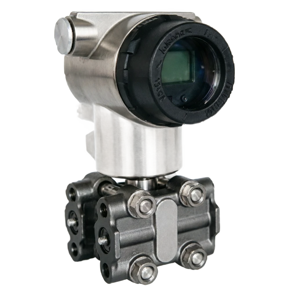
Single-crystal silvial differential transducer

Differential measurement relates the difference between high-side pressure Pₕ and low-side pressure Pₗ, ΔP = Pₕ − Pₗ, to the process variable. A monocrystalline silicon sensing element consists of two symmetrical pressure chambers and a central silicon chip. Differential pressure bends the silicon diaphragm. A diffused Wheatstone bridge or a variable-capacitance structure converts that deflection into an electrical signal proportional to differential pressure. The silicon’s elastic recovery produces very little mechanical hysteresis or creep, improving long-term stability over conventional strain gauges.

  1. 01

    Liquid: ⁇ P = old g H (Line column static pressure differential)

  2. 02

    Flows: ⁇ P ⁇ Q² (associated with the throttle meter)

  3. 03

    Filter resistance: ⁇ P =P -Pin out

  4. 04

    1 High pressure profile . Provide P<sub>H</sub>

Synthetic Silicon Difference Transmitrator Selection Support

Provide survey missions, media and installation conditions and obtain product configuration advice.

Contact us
Single-crystal silica differential transmitter . Technical Note

TECHNOLOGY & APPLICATION

Understand the principles, the exact selection.

From measurement principles to field applications, the technical characteristics and selection features of single-crystal silica differential transporters are understood.

01

TECHNICAL GUIDE

Overview

The differential pressure ( ⁇ P) gauges based on single-crystal silicular sensitive elements carry flow ±0.075% FS) and superlong stability in the automation of industrial processes, and also support flexible engineering applications for differential measurements.

This product, by measuring the differential signals between the high pressure side (H) and the low pressure side (L), combined flow formulas (e.g. the difference pressure and the opening of the flow) or liquid bit formulas ( ⁇ P=old gH), is widely used for the measurement of the corresponding pressure of flow meters such as porosity/nozzle/vine, and for the position of the compact container, interface, filter pressure differentials, heat exchange resistance, etc.

Based on high-scale ratio (up to 100)

1 ~ 200: 1, low-pressure error, one-way excess resistance and full-fledged intelligent diagnostic functions, and single-crystal differential transmitter has become a trade measurement, precision control, high-end processor. This document will be presented in a systematic manner in six areas: rationale, structure, strengths and weaknesses, applications, parameters and selection.

  1. 01

    It combines mature monocrystals processes with the depth of the differential sensor technology, with a very high precision of a single-crystalsil pressure transmitter (±0.04% FS)

  2. 02

    MEMS ~

02

MEASUREMENT PRINCIPLE

Operating principle

2.1 Basis of differential measurements

The differential measurement is based on the core idea of "two points of pressure differential reflecting changes in process parameters".

HL between HL and P

⁇ P = P -P has a defined physical relationship with the variable of the measured process. For example: H L

  1. 01

    Liquid Level

    = old g H (Line column static pressure differential)

  2. 02

    Flows

    ⁇ P ⁇ Q² (associated with the throttle meter)

  3. 03

    Filter resistance

    ΔP = P − Pin out

The above physical relationship allows the reverse of the liquid level, flow or pressure differential by the ⁇ P.

2.2 Silicate differential sensitivity principle

Single-crystally-discretioned sensitive elements consist of two symmetrical pressure cavities (high-pressure and low-pressure cavities) and central single-crystalic chips. When the differential pressure is on both sides of the chip, the silica is subject to different pressures and bending changes on both sides, resulting in a diffusion of the Whistlen bridge (or variable capacitation structure) into a telecommunications signal that is associated with the differential linearity of the pressure. With the introduction of single-crystal silicon, chips have the desired flexible response properties, with almost no mechanical lag and creeping, and long-term stability is significantly better than traditional response films.

2.3 Signal processing process

The micro differential voltage (or the electrical capacity signal) of the bridge-way output is amplified by multiple stages of the ASIC chip, temperature compensation (PTAT circuit + multipoint digital calibration), non-linear correction, converted to 4-20 MA standard industrial signal via DAC and superseded with HART 7 digital communication. Some high-end models also support FUNDATION Fieldbus, PROFIBUS-PA, etc. on-site bus protocols.

2.4. Pass paths

Page 3

2.5 Silent and overpressure properties

Static Pressure is a reference pressure that is shared by high pressure sides and low pressure sides, also known as working pressure. The differential transporter, although measured by the differential pressure, is subject to asymmetric effects that introduce the error, so the high-end model gives the "silence effect" indicator.

At the same time, the differential transporter shall have a strong anti-uni-directional overpressure capability to avoid damage to sensitive elements when the pressure valve on one side is wrongly switched or when the sequester fluid is injected.

Page 4

Motion of work . Serial number / chainCross-reference
Serial numberLinkFunctional description
1High pressure side mediumProvide P<sub>H</sub>
Motion of work . 2 / Low pressure side mediumCross-reference
2Low pressure side mediumProvide P<sub>L</sub>
3Pressure extraction device (prission tube / Frank)Take both sides of the pressure.
5Single-crystal silhouette chipConverting the pressure differentials from both sides to telecommunications
6ASIC Zooming in.Magnification, temperature compensation, linearity
7Microprocessor / DACDigital processing, conversion to standard signal
8Output signal4–20 mA + HART / FF / PROFIBUS-PA
03

PRODUCT STRUCTURE

Product structure

3.1 Typical structural composition

It can be divided into two basic knots: "directly pressured" and "discharged" (with French)

The core structure is as follows:

3.2 Direct pressure differential versus remote transfer

3.3 Typical structural illustrations (text description)

High pressure side extraction mouth (1) ⁇ Isolated film (3) Filled fluid (4) ⁇ Single crystal silicon differential chip (5, high pressure side) ⁇ Single crystal silicon differential chip (5, low pressure side) ⁇ Filled fluid (4) ⁇ Isolated film (3) low pressure side extracter (2).

The differential signal of the differential chip sense is processed by the ASC and microprocessor, and is exported by the wire endpoint 4-20 mA + HART standard industrial signal.

Page 5

& High pressure side-push

Main function: Connect to high pressure side process pipe / packagings Common material / Specification 1/2 NPT/ M20/ Frank / Remote French

Low & side-push

Main function: Connect low pressure side process pipe / packagings Usual material / Specification 1/2 NPT/ M20/ Frank / Remote French

Separating film (optional)

Main function: Protection of single crystal silicon chips, isolation of corrosive media Common material / Specification: 316L / Haps, C-276/ tantalum / Monar

Filling fluid (optional)

Main function: Transfer of pressure, provision of temperature compensation, common materials / Specifications: Silicon / Fluorine / food-grade vegetable oil

Single-crystal silhouette chip

Main function: Core measurement unit, convert ⁇ P to telecommunications, commonly used materials / Specification: Single crystal silicon pressure resistance / Single crystal silicon cones

ASIC Zooming in.

Main function: signal adjustment, magnification, temperature compensation

Microprocessor / EEPROM

Main function: Digital signal processing, parameter storage, common materials / Specifications: MMU + EEPROM / Iron electric storage

Shell

Main function: Protect internal components and provide electrical interfaces Usual materials / Specifications: Aluminium alloy / 316L

Show Header

Main function: On-site display of measurements and diagnostic information Common mass / Specification: LCD (optional backlight / touch)

Connector End

Main function: Power and signal output interface Common material / Specification: Gold plating / Spring

Comparative

Component name: Direct differential pressure type. Primary function: Remote transfer type Usage material / Specification:

Extract Path

Component name: Direct pressure of the carrier body: Primary function: Expedition Franc + Cystreal pressure Common material / Specification:

Typical applications

Component name: Clean, low viscosity, non-corrosive media. Main function: slime, corrosive, crystallable / high temperature / long distance Usual material / specification:

Response speed

Component name: Very fast Main function: A little slow (cracked by a cavity tube) Usual material / Specification:

Still pressure.

Component name: ≤ 40 MPa Main function: Common ≤ 16 MPa material / Specifications:

Installation Space

Component name: Must be close to the pressure point. Primary function: to avoid dangerous or high temperature. Usual material / specification:

Price

Component name: Lower Primary function: Higher (including remote components) Usual material / Specifications:

04

TECHNICAL GUIDE

Analysis of strengths and weaknesses

4.1 Main advantages

Very high measure single crystalline silicon pressure

Specification: Sensitive element with precision up to ±0.04% FS ~ ±0.075% FS, which is the precision of an industrial differential transmitter

Super long, steady, long-term stability.

Specific: ± 0.1% FS / 5 years, partial model up to ± 0.1% FS / 10 years, significantly reducing periodic frequency

High scale ratio

Specification: Bicata 100: 1 ~ 200: 1, a set of transmitters that can cover multiple range requirements and facilitate instrumentation standards

The pressure is low. The pressure is not good.

Specification: The difference can be controlled within ±0.1% FS / 10 MPa, which is significantly better than the traditional differential carrier ±0.5

Strongly resist one-way over-pressurized one-way

Specific: Overpressure ≥ 16 MPa / ≥ 25 MPa to effectively prevent sensitivity caused by mishandling

Quiet pressure boost, etc., to provide level 16 MP

Specific: a / 25 MPa / 40 MPa, multi-symmetric level, suitable for high pressure reactor, water-infusion gas

Smart diagnostics are strong, HART.

Specific: 7 / FF / PROFIBUS-PA bus, allowing remote zero / Quantification, self-diagnosing and pre-medication

The range is wide from 0-0.2

Specific: kPa micropressure to 0-2 MPa can be covered, meeting flow / liquid level / interface / pressure variance

Disadvantages and use restrictions

Single-crystal silica, single-crystal silica.

Response recommendation: The film is highly resilient but has a low mechanical impact resistance and may result in a strong water hammer or vibration

Prices higher than M-E MMS process

Response proposal: Chip + Complex ASIC pushes up manufacturing costs at about 1 of the conventional differential transmitters

The installation of the package is highly demanding

Proposal for response measures: Quantification will require three valves, balancing valves and condensers, etc., and installation debugging is relatively complex

Direct differential pressure resistant to corrosion

Response measures recommend that the in-house pressure structure is resistant to strong corrosiveness and that the strong corrosive medium requires the choice of long-range or diaphragm structure.

Zero points drifting on the side of the single question.

Response response measures suggest that zero-point drift may occur as a result of stress, temperature change, and that the distance of HART is verified or selected on a regular basis

The lower limit of the scale is MEMS.

Response response recommendation: eclectic and bridge circuit resistance restrictions, microdifference (< 0.1 kPa) measurement accuracy affected, need to be selected for special use

05

APPLICATIONS

Application area

It is a core instrument for flow, fluid, interface, resistance measurement scenes, and is widely used in the following industries: 6 page, 7 page

Flow measurement (scaling hole panels) / Spray

Typical application scenario: traffic in steam, gas, liquid, etc., bygone voltagers, etc., porridge / / V cones

Liquefied Level Measurement

Typical application scenarios: closed container liquid level (compensation with static pressure), constant pressure tank fluid level, boiler-pack fluid level.

Interfacing measurement

Typical application scenarios: separation interface, oil-alkaline interface, oil-acid emulsion interface, etc., calculation of interfaces based on two phase-density differences

Gas fields

Typical application scenarios: crude oil separators, sink tanks, EDU interfaces and fluid levels, water-injecting gas well flow monitoring.

Petroleum chemicals

Typical application scenarios: reaction plume, distillation tower plate differential pressure, heat exchanger resistance precipitation monitoring.

Electricity

Typical application scenario: boiler-to-basket flow, condensed flow, high pressure heater fluids and differential pressure.

Metal and metal

Typical application scenarios: gas differentials on top of furnaces, liquid levels of the casting crystallizer, feedback from hydraulic server systems.

Environmental protection of water treatment

Resisting pool, adding to drug flow, and anti-permeability differential monitoring.

Paper industry

Slurry pool fluids, boiler-dipplenium differential pressure, white water recovery system flow.

Laboratory and metrology

Standard flow units, calibration devices.

06

TECHNICAL SPECIFICATIONS

Technical Parameter Table

The following parameters are generic technical indicators for typical single-crystal-silli-disk transmitters, and the actual product parameters are based on the manufacturer's exit data sheet.

Page 8

Technical parameter table · Parameter item / Specification parameterCross-reference
Parameters itemSpecification parametersRemarks
Sensitive shapesSingle-crystal silicon pressure resistance / single-crystal silicon capacitor (MEMS process)Very few of them have chip autonomy.
Pressure range0-0.2 kPa ~ 0-2 MPa( ⁇ P) optional0-0.1 kPa microvariate to 0-10 MPa large
Silent pressure level0–16 MPa / 0–25 MPa / 0–40 MPaSelected based on the pressure of work on site
Turndown ratio100:1 ~ 200:1Some high-end models can reach 400:1
Accuracy class±0.04%FS / ±0.075%FS / ±0.1%FSHigh-end model up to ±0.025% FS
Long-term stability± 0.1% FS / 5-10 yearsAbout 5-10 times the traditional film replica.
The impact of static pressure±0.1%FS / 10 MPa ~ ±0.3%FS / 40 MPaBetter than traditional ±0.5% FS
Output signal4-20 MA + HART 7 (two-line) optionalFF / PROFIBUS-PA / WirelessH
Electricity voltage10.5–45 V DC (Standard Type)Benz 10.5-30 V DC
Load capacity0–600 Ω(HART ≥ 250 Ω)It depends on the power voltage.
Process medium temperature40 °C ~ + 120 °C (direct pressure)Teleported condensers up to +400 °C
Ambient temperature40 ℃ ~ +85 ℃Show the header -20 °C ~ +70 °C
Environmental humidity5% ~ 95% RHNo condensation
Ingress protectionIP65 / IP67 / IP68IP68 for prolonged underwater settings
Explosion protection markingExia ⅡC T6 Ga / Exd ⅡC T6 GbBased on GB/T 3836
Electrical connectionM20×1.5 / 1/2 NPTYou can choose the one that's gonna blow up.
Process connection1/2 NPT/ M20/ Frank/ Faraway FrancBased on media and field work
Anti-unilateral overpressureH side ≥ 16 MPa / L side ≥ 16 MPaQuiet pressure type up to 25 / 40 MPa
Temperature effects (total error)±0.2%FS / 50 ℃ ~ ±0.3%FS / 100 ℃Better than traditional ±0.5% FS
Response time≤ 80 ms. (Destructed 0 — 60 s)Electrical and mechanical blockages
WeightAbout 3-5 kg (direct pressure)Teletransmitable 8-10 kg
Body materialAluminium alloy (spray)/ stainless steel 316LPreservative grade options
Communications agreementsHART 7 / WirelessHART / FF / PROFIBUS-PAOptional Smart Diagnosis
AuthenticationCE / ATEX / IECEx / NEPSI / CCCMeasurement CMC Authentication Optional
07

SELECTION GUIDE

Select Table

This section provides selected reference for four dimensions of "discretionary" scale, "static level", "applied scene", and "process connecting" to allow engineers to quickly locate the model.

7.1 Table of options for the range rate

7.2 Table of types by static pressure level

7.3. Table of types by application

Page 9

7.4 Process Connection Form Spacing Table

Page 10

Selecting table . The quantum code / the margin rangeCross-reference
The quantum code.The range of pressureSilent pressure levelTypical applications
RC-010–0.1 ~ 1 kPa0–16 MPaSmall flow, low pressure gas flow.
RC-020–1 ~ 6 kPa0–16 MPaGeneral liquid / gas flow
RC-030–6 ~ 40 kPa0–25 MPaVapour flow, constant pressure container fluid level
RC-040–40 ~ 200 kPa0–25 MPaHigh pressure vapour, closed container liquid level
RC-050–0.2 ~ 1 MPa0–40 MPaHigh pressure liquids, boilers, water
RC-060–1 ~ 2 MPa0–40 MPaSuper-high pressure hydraulics, water injection systems
RC-V±0.5 kPa / ±2 kPa0–16 MPaInterface, pressure monitoring
Still-pressure codeSilent pressure levelTypical applications
SP-A0–16 MPaGeneral process pipes, tanks, response pads
SP-B0–25 MPaHigh pressure steam, high pressure gas, water wells
SP-C0–40 MPaSuper-high pressure reactor, deep well water injection, oil and gas wellheads
SP-D0–10 MPaThe pressure system, air conditioning, building control.
ApplicationsMedia FeaturesSuggested selection elements
Fluid flow (steam)High temperature, water, condensableRC-04 + Balance Container / Condensate Can + High still pressure SP-B
Fluorine (gas)Low pressure, low Renault.RC-02 ~ RC-03 + Straight-drive integrator
Fluorine (liquid)Clean, low viscosityRC-03 + Triple valve group + Deposition tank exhaust
Boiler bag liquid levelHigh temperature, high pressure waterRC-04 + Double Room Balance Container + Remote Migration
Oilwater Separator InterfaceTwo-phase, small density differenceRC-V Two-way ±2 kPa+ Interface algorithm
Filters' pressure differential monitoringBlockable mediaRC-02 + High Uno Overpressure + Self-diagnostic
Water slot in the storage tank (closed and pressurized)Increased density compensation is required.RC-04 + Density Input + Remote Zero Move
Trade measurement±0.04% FS, CMC authentication requiredHigh Precision PR-A + NEPSI / CMC Measurement Authentication
LUD / LPG interfaceDeep cold - 196 °CR-04 + cryogenic filler
Table of choice · Corrosive media flows / Strong acid alkalis, organic solventsCross-reference
Corrosive media flowStrong acid alkaline, organic solventRemote + Haps, C-276, film + fluorine
Connection codeFormSuitable operating conditions
C-N121/2 NPT inner screw (standard)Common pipe, flow / liquid level
C-M20M20x1.5 Thick insideEU, Industrial General
C-G12G1/2 Inner screwO-Bill, building control.
C-F25PN25 Frank (small)Low pressure differential, low viscosity
C-F50NN50 Frank (standard)Medium pressure flow, liquid level
C-Tri50DN50 Tri-ClampHealth level, food / medicine
C-RemoteRemotely pass French componentSticky / corrosive / high temperature / long range
08

SELECTION GUIDE

Selection of guidance and attention

8.1 Selective Steps

8.2 Installation and use of attention

  1. 01

    The flow measurement shall be accompanied by a trivalve (high pressure valve/ balance valve/ low pressure valve) to allow balancing operations during transport and overhaul.

  2. 02

    The launch shall be preceded by the opening of a balancing valve, which shall be slowly open, and the low pressure valve shall prevent a single-side overpressure impact sensitive component.

  3. 03

    The vapour measurement shall contain the condensed tank and ensure consistency of the condensed fluids on both sides, avoiding the introduction of additional pressure errors in the condensed fluid column.

  4. 04

    The altitude difference between the carrier and the extraction point at the time of liquid position measurement requires a zero-point migration correction.

  5. 05

    The installation should be located far from the vibration source, the electromagnetic interference source and, if necessary, the devibrancy support frame.

  6. 06

    The circuit boards and sensitive elements are electrostatic and must be fitted and maintained with static bracelets.

  7. 07

    Direct exposure of hard matter to the surface of the isolated film or to single-crystal silic sensitive elements is strictly prohibited.

  8. 08

    Zero and full mass verification shall be performed before shipment using the HART matrix congener parameters.

  9. 09

    Periodically check the integrity of the shell seal, the Gran Head, and the cable shield.

  10. 10

    Trade settlement differential transmitters should be sent regularly to the national measurement control protocol.

8.3 Maintenance and troubleshooting

Page 11 - End of Document -

Selected guidance and attention . Steps / Key elementsCross-reference
StepsKey elements
Step 1 . Clear measurement missionIdentification is a flow/ fluid/ interface/pressure measurement, specifying the range of the differential, the density of the medium, the temperature of the process.
Step 2 . Calculate the range of differential pressure byMaximum pressure based on maximum workflow / fluid level and selected deviation specification based on 1/3 ~ 2/3 Quantities
Step 3 . Select the static pressure levelSelect the SP-A ~SP-D static pressure level based on the maximum working pressure of the container / pipe.
Step 4 . Select the precision levelSelect PR-A ~ PR-D based on process needs (measurement/ control/ monitoring).
Step 5 Selecting the structure formSelect the direct pressure difference / remote transfer type based on the medium cleanness and corrosivity.
Step 6 . Selecting film and filling fluidsThe long-distance model shall select the film and filling liquid material based on the corrosiveness and temperature of the medium.
Step 7 . Selected Process ConnectionsThe thread, French or sanitary level is selected according to the specifications of the pipe and the field conditions.
Step 8 . Confirm output signalSelect 4-20 maA + HART or FF/ PROFIBUS-PA bus protocol.
Step 9 Safety and certificationSelection of blast-proofing levels based on hazard areas on site; clear trade measurement CMC / NEPSI measurement certification requirements.
Selection guidelines and attention · Common failures / Possible causesCross-reference
Common malfunctionsPossible causeSuggested measures
Output constant 4 maA or 20 maAPower supply abnormal / connection opening / film fractureCheck the power supply, check the circuits, watch the film.
Output is not consistent with flow/ fluid levelThe / Zero point drift / Media temperatureRe-design, check temperature compensation, fix density
Zero points are drifting badly.Unilateral pressure/ installation stress / static pressure effectUse balance valves to reset, re-install, move remotely
Communication Failed (HART)Loaded electrical resistance < 250 / interference / protocol versionCheck load resistance, use shield cables
Selective guidance and attention · Output highly volatile / Media pulse / barbed-up / Too small for block-nithingCross-reference
The output is highly volatile.Media Pulse / Thrust Block / BlockingIncrease in the number of blockers, cleaning of the barbed wires, and filling of buffer tanks
Show anomalies/ noneHeader failure/ power supply is inadequateCheck LCD module and power supply
The static pressure is very different.Low / UncorrectedUpgrade static grade, restatic calibration