
PRODUCT TECHNOLOGY

Switch input, relay output barrier SA6110

Operating principle

Switch input, relay output barrier SA6110 .

The fence provides a energy-limited Ben-Ann detection circuit to the switch on the hazard side or close to the switch (opening the circuit with electrical voltage approximately) 8 The currents of the short circuits are about 8 mA. When the site is closed or disconnected, the circuit current changes and the relative circuit base within the module The current threshold determines the state of the switch and is then driven by photo-separation to secure side relay actions. The complete link is as follows: 1 Dangerous sideburn distribution: provide approximately 8 V open circuit, approximately 8 MA Energy-limited detection power sources for short-circuit currents; 2 Returning current detection: a circuit is considered to be "connected" when the on-site closing or circuit current is greater than 2.1 MA, and circuit current is less than 1.2 MA is considered to be "disconnected" (between 1.2 ~2.1 MA is a lag zone, preventing ads
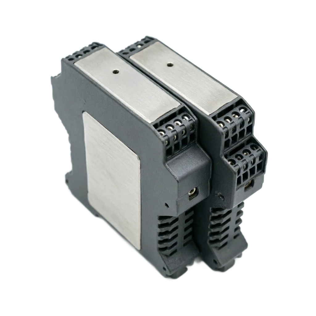
Switch input, relay output separation fence, sub-reference SA6110
Switch input, relay output barrier SA6110 . Classification reference diagram

Switch input, relay output barrier SA6110 selected support

Provide survey missions, media and installation conditions and obtain product configuration advice.

Contact us
Switch input, relay output barrier SA6110 Technical Note

TECHNOLOGY & APPLICATION

Understand the principles, the exact selection.

From measurement principles to field applications, learn about switch input, technical features and selection points of relay output barrier SA6110.

01

TECHNICAL GUIDE

Switch input, relay output separation grid SA6110 Technical summary

Page 1 WorkBuddy Collapse Switch input, relay output separation fence SA6110 Technical summary SA6110 Switch Input / Relay Output Isolation Barrier Technical summary report Document Name Switch input, relay output separation grid SA6110 Technical summary Document Version V1.0 Date of preparation 2026 Year 09 Month 28 Day Scope of content The rationale • Structure • Strengths and disadvantages • Field of application • Technical parameters • Selecting

Switch input, relay output separation grid SA6110 Technical summary Page 2 WorkBuddy Collapse I. GENERAL Switch input, relay output fence SA6110 is a super thin (15 mm) (b) A single-channel switch signal separation safety fence. It receives from the danger zone (Zone 0, Sector 1, Sector 2) ..the main key is the main switch, the NAMUR is the equivalent of the DIN 19234 switch signal, which is restricted by pressure, flow limit. After that, the side of the security electromagnetic relay was driven by photo-separation, and ultimately by a passive SPST The contact (NO/COM) format transmits the situation to control systems such as PLC, DCS, etc. The module uses a triple-separation structure for power, input and output, requiring independent 24 VDC power; panel dialing switches allows input/lost A single or reverse control setting with an input circuit breakout detection alert, with a channel status directly indicated by panel LED. Model system: SA6110 for one in and out of (one channel); this Anam-detonated explosive model after the model with a suffix of `-EX' and usable for IIA, IIB, IIC, T4 ~T6 Explosive gas environment for temperature groups; if two channels or constant (NC) contact points are required, select the same range of standard widths SA 6120 (two in two outs, SPDT).

Switch input, relay output fence SA6110 Technical summary 3 WorkBuddy

02

MEASUREMENT PRINCIPLE

II. Rationale

03

MEASUREMENT PRINCIPLE

2.1 Signal links and conversion principles

The fence provides a energy-limited Ben-Ann detection circuit to the switch on the hazard side or close to the switch (opening the circuit with electrical voltage approximately) 8 The currents of the short circuits are about 8 mA. When the site is closed or disconnected, the circuit current changes and the relative circuit base within the module The current threshold determines the state of the switch and is then driven by photo-separation to secure side relay actions. The complete link is as follows: 1 Dangerous sideburn distribution: provide approximately 8 V open circuit, approximately 8 MA Energy-limited detection power sources for short-circuit currents; 2 Returning current detection: a circuit is considered to be "connected" when the on-site closing or circuit current is greater than 2.1 MA, and circuit current is less than 1.2 MA is determined to be "disconnected" (between 1.2 ~2.1 MA is a lag zone to prevent critical shaking); 3 Photo-electric isolation: results of detections are passed through the light and to the safety side, cutting off electrical access between the hazard side and the safety side; 4 Relay output: drive small electromagnetic relays at NO/COM passive contact point to DI in PLC/DCS The channel provides a dry point signal; 5 Directions and Settings: Channel Yellow LEDs are simultaneously lighted with contact status, green LEDs indicate power is normal; dial switches K1, K2 is used for the same/reverse settings. 2.2 Triple isolation and energy limitation The module uses a triple isolation measure for power transformers, signal photovoltaics, output relays, power, input, transmission Two or two electrical separations between the three; 2500 VAC, 1 min of time, between the insulation of the insulation of the present and the non-insistence. Danger side back. The limit, limit flow element in the road limits the spark energy in a malfunction to below the ignition threshold, thereby ensuring that `activation first, then break' It's impossible to do that.

04

MEASUREMENT PRINCIPLE

2.3 Disconnection detection principles

Place panel to pull switch K3 in an enabling position and connect the switch to one 10 k of electrical resistance, and then the module can be distinguished The two states of "switch is normally disconnected" and "returning lines" are: there are still small and connected circuits when the switch is normally disconnected, and there are no electrical circuits that are electrically blocked. The circuit break-off is zero, and the module determines the break-off and gives warning instructions that the locks resulting from the break-up of the cable are effectively avoided The signal's lost. 2.4 Consistency/reverse control K1, K2 can set the logical relationship between input and output by dialing switches through panels: in the same way, on-site off-switch relays Close; the reverse logic is counterproductive, allowing for matching control systems with different logical polarity, without the need to modify the software configuration.

Switch input, relay output fence SA6110 Technical summary 4 WorkBuddy

05

PRODUCT STRUCTURE

III. The overall structure

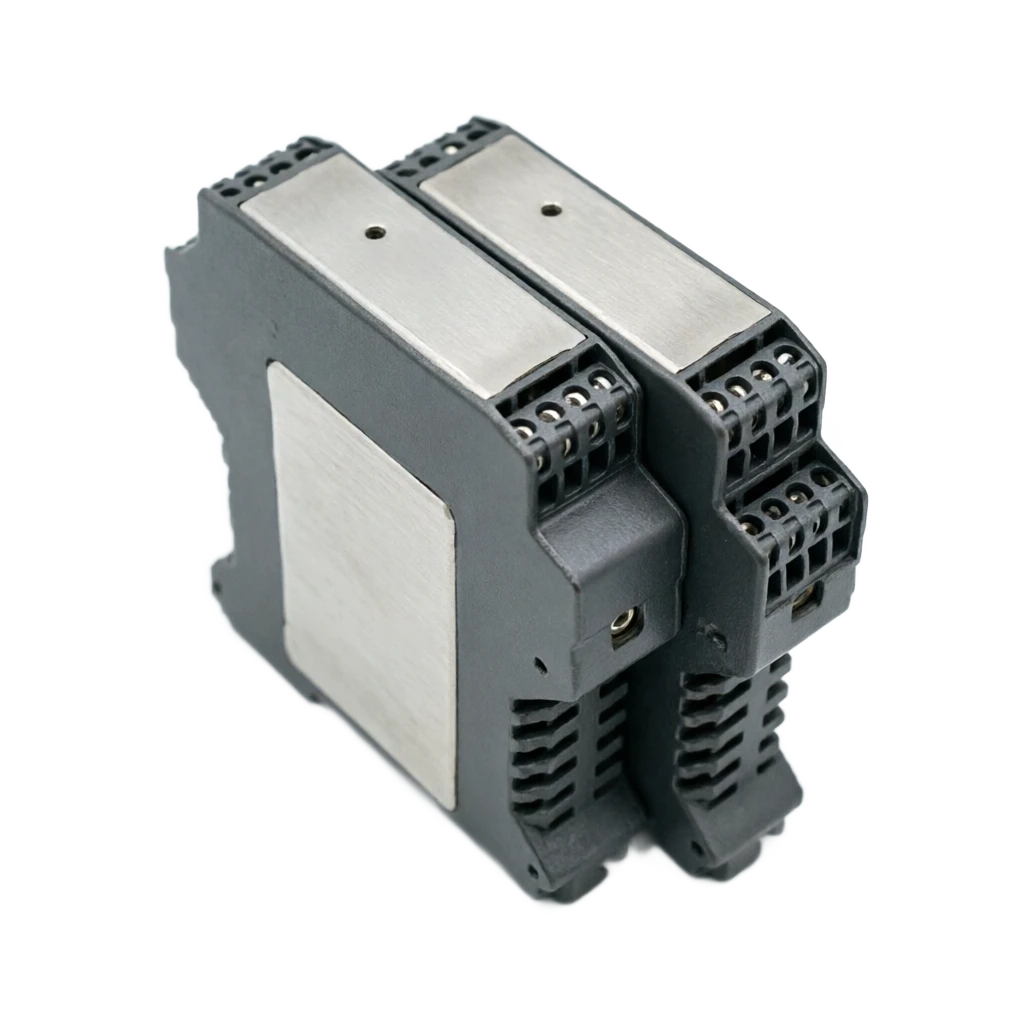
SA6110 Install modules for thin DIN tracks, with no screens on the front, and all external connections are concentrated on a row of vertical ends. The cabinets can be installed in parallel and intensive. The main components are set out below: Serial number Widget Name Main functions Structural characteristics 1 Super thin shell. Protection from electrical body isolation About 15 mm narrow, light ash flame retardant engineering plastics, protection level IP20 2 Lined Sub-Call Power, input, output connection Front column stand alone 6 end (power +/-, input IN0+/-, output COM/NO), big twister screws 3 Status indicator Run and Channel Status Directive Green Power Lantern (PWR)+ Yellow Channel Status Label (IN) 4 Dial Switch Team Function Settings K1, K2 settings are identical/reverse; K3 enables break-through detection 5 Enter detection circuit Ben Ann's power distribution and state are different. The supply of approximately 8 V/8 MA detection power to the hazard side, compared with the lateness of the 2.1 MA/1.2 MA threshold 6 Blocking the circuits. Zone of danger and electrical isolation from security zone Power transformer isolation + signal photo-electric isolation, insulation strength 2,500 VAC 7 Output relay Unsourced Point Output SPST Single Contact (NO/COM), 250 VAC 2A or 30 VDC 2A Block Load 8 DIN Trail Card button Quickly install dismantling Bottom standard DIN35, rail card assembly structure On the surface, the head of the module is marked by a state sign from top down, a vertical line end and model, and the bottom by a track card button; Block modules are only about 15 mm thick, with dozens of channels installed on a standard 1 m long track, especially for high density in large cabinets D.I. signal isolation modification.

Switch input, relay output separation grid SA6110 Technical summary Page 5 WorkBuddy Collapse IV. ANALYSIS OF POSSIBLE AND NEGOTIATIONS 4.1 Main advantages 1 Super thin (approximately 15 mm), single channel independent seal, high utilization of cabinet space, especially suitable for high density DI (b) Segregation; 2 Three-fold power, input, output separation, no inter-traffic interlocking, single point failure non-proliferation and high intervention resistance;

06

PRODUCT STRUCTURE

3 This Angular Explosive Protection Structure (-EX) is available for 0/1/2

Area, IIA/IIB/IIC, T4 ~ T6, direct access to hazard area field switches; 4 output is an passive relay dry point, naturally compatible with the DI modules of the brand PLC/DCS, and does not need to be matched with the level; 5 has input break-line detection and compost/reverse capability to debug grouping in a flexible manner to predispose cable breakers; 6 response time is not greater than 20 ms, and the power supply range 20 ~ 35 VDC is wide and adapts to the fluctuations in power supply on the ground; 7 NamUR near the switch is directly accessible and is powered by a security fence without additional power supply on site. 4.2 ' s main shortcomings and limitations (a) 1 single channel design, with a large number of modules required when DDI points are larger, and an increase in the number of insider connections; 2 output is only SPST (NO/COM) contact point, which does not provide a constant (NC) contact point or double-drop switch, and this needs to be replaced SA6120; 3 mechanical relays have an action lifetime (the electrical lifetime is about 100000 by weight) and are not suitable for high frequency (HF) action; 4 contact capacity is limited to 2 A (retardant) and direct-driving large current contactors require external connection to intermediate relays; 5 requires independent 24 VDC power supply, which is small (approximately 50 mA) but adds to the inner-box circuit design;

07

TECHNICAL SPECIFICATIONS

6 No field displays with parameter alignment interfaces, functional settings rely only on panel to pull switches and state confirmation is less intelligent than smart visual.

Switch input, relay output fence SA6110 Technical summary 6 WorkBuddy

08

APPLICATIONS

V. APPLICATION AREAS

The SA6110 safely brings discrete signals from hazardous areas into control systems. It is widely used in process control and safety interlocks in petrochemical, chemical, oil and gas, and pharmaceutical facilities. Item Industry Typical application 1 Petrochemicals Connect hazardous-area pressure, level, temperature and valve limit switches to DCS/SIS interlock circuits. 2 Oil and gas production, storage and transport Isolate pump status, local emergency-stop buttons and tank-farm high and low level alarms in areas with flammable gases. 3 Pharmaceuticals and specialty chemicals Isolate and condition reactor agitator feedback, inlet and outlet valve positions, and cleanroom interlock signals. 4 Metals and power generation Send conveyor interlocks and auxiliary contacts from circuit breakers and switches to SCADA, reducing ground-loop currents. 5 Water treatment and municipal services Isolate float and level switch inputs from pump stations and dosing rooms to the PLC. 6 General industrial automation Isolate PLC digital inputs from field switches to address common-ground interference and signal crosstalk. Consider this barrier when field switches are in hazardous Zones 0/1/2 or when ground potential differences or coupled interference between switches and the control system require electrical isolation and energy limitation.

Switch input, relay output fence SA6110 Technical summary 7 WorkBuddy

09

TECHNICAL SPECIFICATIONS

VI. MAIN TECHNOLOGICAL APARANTS

The following are the main technical parameters of SA6110 (based on typical manufacturers ' publicly available sample data, and based on random instructions): Parameter Item Specifications Product Model SA6110 (one-way channel, super thin); this is SA6110-EX Enter the number of channels 1 Road (hazardous side) Type of input signal Unsourced Switch Contact, NAMU Approach Switch (compatible with DIN 19234), Beneficial Pressure/temperature/Line Level Switch, etc. Dangerous side power distribution Open circuits for electrical voltage of about 8 V; short circuit currents of about 8 MA Action threshold Same settings: circuit currents greater than 2.1 MA relay adsorption; less than 1.2 MA relay releases (delay zone 1.2~2.1 MA) Response Time Not greater than 20 ms Output Form 1 Road SPST Relay Non-Resource Contact (NO/COM) Contact Capacity 250 VAC 2 A or 30 VDC 2 A (extreme load) Break-through detection support; dialing switch K3 energy, field switch links 10 k stops Same/reverse settings Panel Dial Switch K1, K2 Settings Electricity voltage 20~35 VDC (independent power supply) Consumption of currents Not greater than 50 maA (24 V power, relay contact closed) Insulation intensity Between Ben and Non-Entity 2,500 VAC, 1 min Embrace GB/T 18268 Industrial equipment application requirements (equivalent to IEC 61326-1) Explosive-proof level Ex ia IIC T4~T6, applicable to the explosive gas environment of the Zone 0/1/2, IA/IIB/IIC class Working environment temperature -20~+60 °C Appearance and installation About 15 mm ultra-shrink, DIN35 standard guidance card set Status indicator Green Power Lantern + Yellow Channel Status Label

Switch input, relay output separation grid SA6110 Technical summary 8 WorkBuddy

10

SELECTION GUIDE

VII. Selected guides and models

11

SELECTION GUIDE

7.1 Summary of Selected Elements

In selecting the models, it is recommended that they be confirmed on a line-by-line basis as shown below, so that no return work is done on site.

Item Selection criterion Options Selection notes 1 Channel count Single-channel SA6110 / dual-channel SA6120 Choose one input and one output or two inputs and two outputs according to the required field points. 2 Contact type SPST (NO/COM) / SPDT (NO/COM/NC) Choose SA6120 when normally closed or changeover contacts are required. 3 Explosion protection General industrial model / intrinsically safe -EX model Select the EX model for Zones 0/1/2, gas groups IIA/IIB/IIC and temperature classes T4–T6. 4 Input device Dry contact / NAMUR proximity switch The barrier supplies approximately 8 V to the proximity switch. No separate field supply is required. 5 Open-circuit detection Required / not required When needed, enable K3 and connect a 10 kΩ resistor across the switch. 6 Logic polarity Non-inverting / inverting Set K1 and K2 on site to match the control system’s digital input logic. 7 Load rating Up to 2 A resistive Use an external interposing relay for larger loads such as contactor coils. 8 Installation density 15 mm slim / standard width Choose the slim model for compact cabinets with a high point count.
12

SELECTION GUIDE

7.2 SA6110 and SA6120

Comparative items SA6110 (super thin single channel) SA6120 (standard two-channel) Channel structure - In and out. Two in and two out. Output Contact SPST(NO/COM) SPDT(NO/COM/NC) Width of Module About 15 mm super narrow Standard width (approximately twice the size of the super thin) Consumption of currents Not greater than 50 ma Not greater than 75 ma Break-through detection Support (K3 + and 10 k) Support (K3 + and 10 k) Apply scene High density DDI quarantine, constant contact output We need a constant contact point, two-channel containment.

13

SELECTION GUIDE

7.3 Examples of typical job profiles

Typical Work Status Recommended Model/Consequence Annotations Large cabinet, D.I., heavy, space-strained. SA6110 15 mm super thin single channel, install by point number The site needs constant closed contact to be involved in the chain. SA6120 SPDT Contact, NO/COM/NC -end complete Risk area 0/1/2 Sector switch signal introduction SA6110-EX Ex ia IIC T4 ~ T6 Ben An NAMUR Approaching Switch Access SA6110 or SA6110-EX 8 V, no power supply for approach switch. The remote switch needs to be disconnected. SA6110 + and associate 10 k + K3 enablers The channel alerts when the line is cut. Driver Contact Circles, etc. Loads 2 A or more SA6110 + Intermediate relay Security fence contact point only 2A, heavy load needs amplification

Switch input, relay output separation grid SA6110 Technical summary Page 9 WorkBuddy Collapse VIII. ELEMENTS FOR ASSIGNMENT AND MAINTENANCE 8.1 Installation Attention 1 Installed on a control chamber standard DIN35 track, with card locks secured after card loading, and modules not subject to suspension of the subdued strength; 2 This circuital circuit cable and non-belonger cables shall be split and bound and shall be distinguished by blue markings; 3 End screws are compacted by the force rectangular of the instructions to prevent the false heat; power 24 VDC is sensitive to positive and negative polarity; 4 When a break-through is required, it is essential that 10 k of electrical resistance be linked to both ends of the on-site switch and that K3 be placed in an enabling position; 5 Multimodules, with intensive deployments, to reserve thermal and wiring operating space at ambient temperatures of no more than 60 °C; 6 The ground system meets the relevant norms by connecting to the site at a single point as required by the present security protection against blast. 8.2 Points for daily maintenance 1 Periodically patrol panel lights: green lights often indicate that the power is normal and yellow lights should be in the same condition as on-site switches; 2 The circuit used for the break-off detection and, in case of break-line alerts, the inspection of the live cables and switch-off lines should be conducted immediately; 3 HF actions or heavy load loops should periodically assess the end of the relay contact period and replace the modules as a whole as necessary; 4 Disconnect power and circuit lines before overhauling or replacing modules, rechecking the same/reverse and breakline detection after track-up replacement Settings; 5 Periodically check whether the end is loose, oxidized and kept clean and dry inside the cabinet to avoid dust and corrosive gas intrusion.

SA6110 discrete-input, relay-output isolation barrier · Technical summary Page 10 Compiled with WorkBuddy 9. Summary The approximately 15 mm wide SA6110 provides single-channel isolation between a hazardous-area switch and a safe-area relay contact. Features include three-way isolation, intrinsic safety, open-circuit detection and selectable non-inverting or inverting logic. Its dry-contact output connects directly to compatible control systems for high-density digital-input isolation in petrochemical, chemical, and oil and gas applications. The unit has one channel, SPST contacts and a 2 A load limit. Use the SA6120 or an external interposing relay for normally closed contacts, two channels or higher loads. The SA6110 is suited to space-constrained, high-point-count intrinsically safe applications that mainly use normally open contacts. — End of document —