PRODUCT TECHNOLOGY

4-20mA output operating end barrier

Operating principle

4-20mA output operational end barrier.

General structure: The integrated operator separation fence of the triple function consists of three parts on the electrical road: signal processing channel, this stationary energy limit and operator human interface. 4 - 20mA input signal (or source 4 - 20mA command) from the control system is converted to voltage by sampling of electrical resistance, and the signal is bound to the side of the site by an isolated transformer (partly with photoelectric coupling); (a) A voltage-flow conversion circuit on the side of Ben An to form 4-20mA constant current output, driving the hazardous area implementation equipment; Valve feedback currents are transferred back to control system in reverse along the independent ABL. The three-fold protection chain of the energy transport path, which is limited in pressure, current, energy limit, ensures that the instant power and energy on the side of the hazard zone are contained within this security parameter. Essentially safe "ia" level requires normal work, a malfunction.

  1. 01

    • The input signal is combined by a high frequency transformer to the side of the site and is adjusted to the simulated amount; Input, output, power source three-way means quarantine above 1500 V AC 1500 ~ 2500 V AC; Isolated capacitor is less than 1 nF

  2. 02

    V/I Conversion Output . Ben An side discharge and power tube constitute a pressure-controlled constant flow source, converting the decomposition controlled voltage to 4-20 MA constant flow output, with load capacity bound by limited power circuits . 4-20 MA; load 0 ~ 300 ~ 550 (subject to authentication parameters)

  3. 03

    • Redundant Zina Clips + restricted current resistance + triple structure for the Meltinger, limiting Uo/Io/Po to the authentication limit, achieving ia double failure safety / typical Uo not greater than 28 V, Io not greater than 93 MA (IIC field viewer type)

  4. 04

    • 4 - 20 mA currents (or feed from a fence locator and detect circuit currents) from the independent input channel receiving valve locator feedback, after isolation with 4 - 20 mA or 1 ~ 5 V delivery control system • Feedback accuracy 0.1 ~ 0.2% FS

4-20mA output operating end separation fence support

Provide survey missions, media and installation conditions and obtain product configuration advice.

Contact us
4-20mA output operating end barrier Technical Note

TECHNOLOGY & APPLICATION

Understand the principles, the exact selection.

From measurement principles to field applications, the technical features and selection elements of the 4-20 mA output operating end separation fence are understood.

01

TECHNICAL GUIDE

Overview

The definition and positioning of the 4 - 20mA output operator separation fence (hereinafter referred to as the operator separation fence) is the inherently safe interface equipment installed in the safety zone (non-explosive hazard zone) or in this safe room for the implementation of the field equipment type of equipment in the hazardous area (explosive hazard zone). It receives 4-20mA control instructions from DCS/PLC/regator (or manually given through its own panel), and exports BAL 4-20m signals to electrical valve locators, electric/gas converters, electric implementing agencies, proportional control valves, etc., after isolation and energy limitation, while re-transmitting the valve feedback to the control system, constituting a two-way sub-routine channel of "Down Command + UpPress".

The name of the operator is derived from its retained manual ability to operate.

When the control system fails or is overhauled, the operator can hand out the 4-20mA output directly on the panel, maintain control over the valve and achieve a no-disturbing switch, the last manual control means for the control of the blast-proof process.

The location fence in the fence family is generally divided into two categories: the Zina security fence (unconnected, dependent on Zina two-way limit) and the isolation fence (inventory, transformer/PVID+ power-restricted circuit). In the direction of the signal, it is divided into input types (danger zone signal entry control system), output types (control signal to hazard area)

The operator separation fence is an enhanced form of an isolated output, with manual performance, valve display and operation output, etc., superimposed on the output limit channel, and is the most complex of the functions of the safety fence family.

Table 1 - 1 Operator Separation Fence in the Safety Fence family origin from the 20 Century 60 British Zina Fence Program, which was based on precision and limited application; 80 After the age of the year, products that integrate the function of the operator on the basis of a separation fence (e.g., MTL5041 / 5042 、P+ FKFD2 The series of operational barriers) is widely available in the petrochemical industry. Since the beginning of the 21st century, Shanghai Self-Deservation, the Tienjin City Central Circle, the Rosmont Agency System in the Far East in Beijing and local producers (such as Nanjing Yubaku, Shanghai Treasure, etc.) have been able to scale up and gradually integrate the HART transmissible, digital and communication diagnostic function.

  1. 01

    The Age transformer's isolation fence has become the mainstream, representing manufacturers including under the flag, Pepperl+Fuchs (P+F), Turk (Turk), R.S.A., and others.

  2. 02

    MTL (now Stahl)

  3. 03

    Eaton, etc. 90

· Project / Operator Separator FenceCross-reference
ItemOperator's barrier.Normal output fence.Zina security fence.
Explosion protection typeEx ia IIC T6 Ga (separated text)Same LeftEx ia IIC (Zina)
Isolation methodElectromagnetic isolation of transformers, input/output/powerThe transformer is quarantined.No quarantine, dependent on the ground system.
Signal directionOutput (control command) + Feedback (valve) -wayUnidirectional OutputUnidirectional (Input or Output Type)
Manual OperationsPanel manually assigned 4-20mA, hand/automatic no-disturbingNoneNone
Valve DisplayDouble header display output/valve, or numericallyLED InstructionsNone
ElectricityDC 24 V system powerDC 24 VNo electricity.
Applicable hazardous area set-upElectrical valve locator, electric/gas converter, electric implementerTransmitters, valve locator, etc.Thisrmoan equipment (required for strict parameter matching)
Installation and maintenanceDIN Track installation, no maintenance, low ground requirementsDIN Track InstallPrecision systems required, high maintenance requirements
02

MEASUREMENT PRINCIPLE

Operating principle

Overall structure

The integrated realization operator separation fence of the triple function consists of three parts on the electrical road: signal processing channel, this fixed energy limit and operator human interface. 4 - 20mA input signal (or source 4 - 20mA command) from the control system converted to voltage by sample electrical resistance, by isolation transformer (partly supported by photoelectric coupling)

(a) Linking signals to the side of Ben-An; (a) A voltage-flow conversion circuit on the side of Ben An to form 4-20mA constant current output, driving the hazardous area implementation equipment; Valve feedback currents are transferred back to control system in reverse along the independent ABL. The three-fold protection chain of the energy transport path, which is limited in pressure, current, energy limit, ensures that the instant power and energy on the side of the hazard zone are contained within this security parameter.

Benz-Capital (ia-level)

The inherently safe "ia" level requires that no explosive mixture be lit at normal work, at a failure and at both (counting) failures. The separation fence is achieved by means of the following: first, a multi-stage laceration of the output voltage by the Zina diode array (redundant diode, single diode failure without loss of protection); Second, limit current resistance to the chain of the output circuit, limiting short-circuit currents to this Ant-parameter; Third, the breaker permanently breaks the circuits during continuous overload, preventing the loss of the energy limitation capability following the deterioration of the protective component; Fourth, the isolation transformer provides electrical isolation and the malfunctioning energy on the side of the safety zone does not allow direct access to the hazard zone. The four-step joint guarantee that Uo, Io and Po, at the output end, meet the required blast-proofing authentication values.

Key subsystems 2-1 Operator Separators Keys Fence Keys Working Parameter Matching Principles (Uo/ Io/ Po and Co/Lo)

The installation of this AMS circuit is subject to the satisfaction of the "danger zone end parameters of the fence" and "inspection parameters of the AVE": Uo is not greater than Ui (the maximum input voltage of the equipment), Io is not greater than Ii, Po is not greater than Pi, while the external electrical caps allowed by the fence are not less than the equivalent of the on-site equipment, Ci, Sensory Lo and Li (Cables are typically estimated at 200 pF/m and 1 uH/km). The output channel of the operator separation fence is checked one by one with the underlying parameters of the valve locator, which is a mandatory check item for selection and circuit design, and is the core element of blast-proofing reviews (e.g. IEC 60079-25 calculations in this system).

Motion of work . Subsystem / Motion of workCross-reference
SubsystemOperating principleKey indicators
Signal quarantine.The input signal is combined with the HF transformer to the side of the site and is adjusted to the simulation; the input, output, power source can be separated from above 1500 V ACIsolated pressure 1500~2500 V AC; Isolated capacitor less than 1 nF
V/I Conversion OutputThis side discharge and power tube constitutes a pressure-controlled constant flow source, converting the decomposition controlled voltage to 4-20 MA constant flow output, and load capacity is limited by energy-restricted circuits.4-20 MA; load 0 ~300 ~ 550 (View authentication parameters)
Ben's energy limit.Redundant Zina Clip + restricted current resistance + three-fold structure of the Meltinger, limiting Uo/ Io/ Po to the authentication limit, achieving ia double failure safetyTypical Uo not greater than 28 V, Io not greater than 93 MA (IIC field viewer type)
Valve Feedback Channel4-20 MA current (or feed from a fence to the locator and detect circuital currents) for receiving valve locator feedback in an independent input channel, 4-20 MA or 1-5 V delivery control system after isolationFeedback accuracy 0.1 ~ 0.2% FS
Manual OperatorPanel bits or keys generate manual values, which are switched by simulated switches to automatic signals; track circuits allow manual values to follow automatic values in real time, toggle instantaneous non-disturbingNo Disturbing Switch margin less than 0.5% FS
Show and StatusDouble-ring tablehead or even-numbered indicator output for given and valve-rate feedback; LED indicator power, failure and channel statePrecision 1.0 ~ 1.5 (head of table) or 0.2 (number)
HART Passage (Selection)Plug in between output and feedback channels to allow the two-way transparent transmission of Bell 202 FSK signals to enable the HART communicator to be organized via the end of the safe zone to the smart locatorHART 5/7; Resisting Resisting HART
Power and protectionDC 24 V Redundant Power Supply (Diode Decomposition), Internal Reverse, Overflow and Wave Protection, when power is lost, Output to Safety (optional)Work: 1~3 W/channel
03

PRODUCT STRUCTURE

Product structure

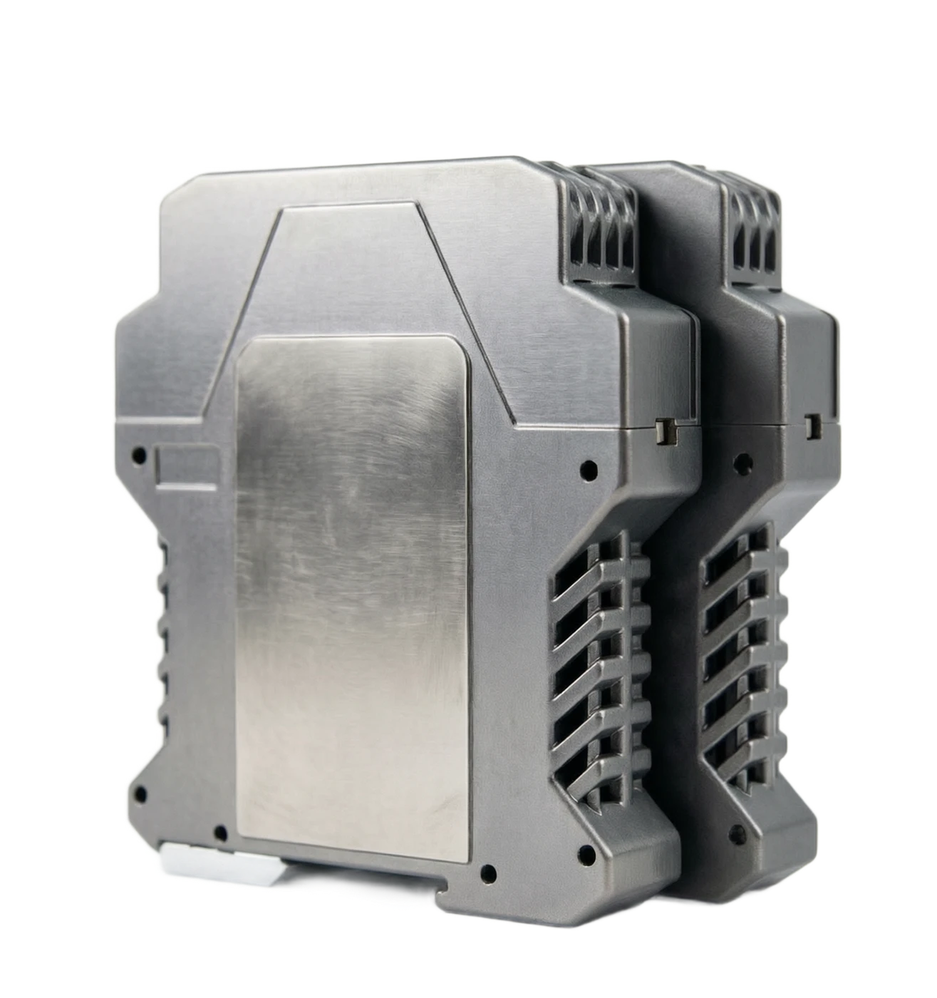
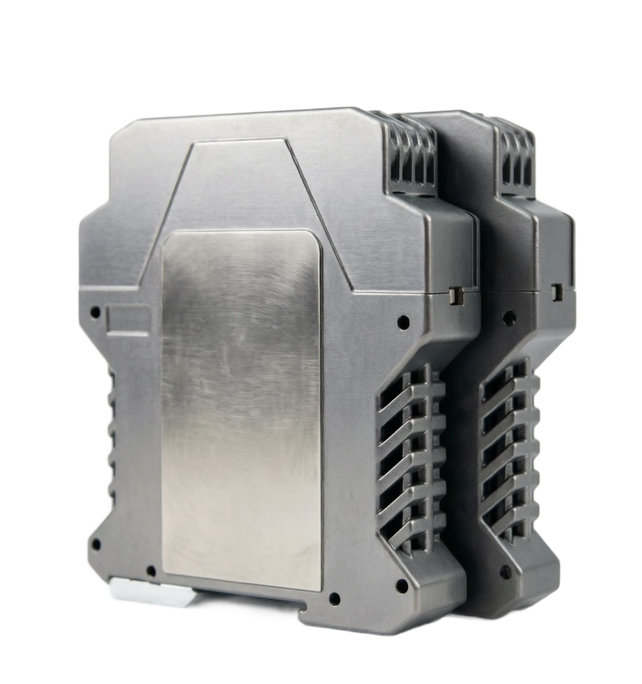
The whole-form operator separation fence is a thin shell with a typical width of 12.5-30 mm and depth of approximately 114 ~124 mm, which can be installed in a high-density column inside the cabinet, using standard DIN 35 mm guidance. The panel (head to the operating side or inside the cabinet depending on the structure) displays the watch, manually gives the knob/key and state indications, the end of the line is located on both sides of the top and lower sides or back, the end of the hazard zone and the end of the safety zone are clearly partitioned in space and marked with an Ex mark to prevent the wrong connection.

Table 3-1 The evolution of the structure of the operator ' s separation fence structure is a trend towards thinness and high density: the width of a single channel has been reduced from 30 mm or more to 12.5 mm, with the power of the conveyance (Busbar) being saved from the power supply to the power supply; Second is intelligent: Numerical + key setting representative header and DIP switches, some of which support the self-diagnostic uploading of malfunctions and PLC side state surveillance; Third is functional compound: output energy limitations, valve feedback, HART telemetry and preservation logic integration into the same shell, and a device can complete the full interface of a built-in reconciliation circuit.

Table of advantages and disadvantages 4-1 Table of main advantages 4-2 Table of main weaknesses and responses

The shell.

Composition and function: Flammable Resisting Project Plastics (PA) or Metals Crusts, DIN Track Card button installation, width 12.5-30 mm (one/two channel) Design elements: flame retardation grade UL94 V-0; The distance and the electrical gap meet IEC 60079-11 requirements.

Display unit

Composition and function: Double-ring table head (two vertical pins) or double-line LED/LCD numbers visible, same screen indicator output given values and valve feedback Design points: table header accuracy 1.0 ~ 1.5; number 0.2 with back light

Manually attributed unit

Composition and function: Multi-ring electric twilight or incremental buttons, generating 0-100% manual given; hand-made/automatic switch and status lights Design elements: error-proofing or confirmation operation; toggle undisturbed design

Isolating transformers

Composition and function: HF ring/EE transformer, energy transfer to carry signal and side power, initial stage shielding, design elements: isolation resistance 1500-2500 V AC; combined caps less than 1 nF, inhibiting commo interference

Benz panel.

Composition and function: Redundant Zina diode, restricted current electrical resistance, smelter and plier circuits, final ring at the end of the hazard zone Design elements: ia double-facing count redundancy; component reduction use, sufficient amount of authentication parameters

Signal processing panel

Composition and function: Modem, V/I and I/V conversion, tracking and switching logic, failure detection and output safety management Design elements: temperature coefficients higher than 100 ppm/°C; breakline/extract detection (optional)

Connector End

Composition and function: Safety zone endpoint (power, input, feedback output) and hazard area endpoint (Ben An output, feedback input) partitioning, to remove cage spring endpoint Design elements: hazard area endpoint blue sign and Ex emblem; Ben An and non-Ben Angle separated

Power unit

Composition and function: DC 24 V power input, diode redundant coupling, internal multiple-routing isolation power source is on the side of the side of the side. Design elements: back-to-back protection; output loss is available for safe placement or movement to 0 MA/100%

Deck and authentication identifier

Composition and function: Marking blast-proof signs (e.g. Ex iIC T6 Ga), authentication number, Uo/Io/Po/Co/Lo Bend parameters and warning words Design elements: verification of consistency with blast-proof certificates is the required inspection item for acceptance

Essential security + electrical isolation double-security

Description: A dual failure security is met, transformer isolation cuts off the transmission path of the faulty energy in the safety zone, blast-proofness is better than the unsegregated Zina fence; system side waves and loop interference are also isolated

Operator function retains manual control

Note: The system failure or drive phase can manually open the valves to the panel, hand/self-disturbed switching, avoid blast-proof zone regulation, circuits lose control when DCS fails, and avoid the risk of manual operation on site

Double-channel, save room in the cabinet.

Note: The command line down and valve feedback up to the same 12.5 ~ 30 mm wide shell, saves approximately half of the two devices with space and connections.

Low grounding requirements. Works are good.

Note: Separated structures require a much lower security fence system than the Zina fence, and the retrofitting project can be made easier by using the existing network.

Transfer accuracy and anti-disruption capability.

Note: Output 0.1 ~ 0.2%-grade precision, isolation inhibiting commode interference (CMR typical 100 dB above), long distance return sign quality stable

Powerable maintenance replacement

Note: The danger zone is sided with the HQ, which allows for the inspection of the sidelinks and replacement of equipment in the safety zone without parking (in accordance with the protocol), and reduced parking of installations

HART Smart Device Passage

Note: The machine type with the HART transmissible can be organized, diagnosed and verified in the safety zone without breaking off the Ben Ang return road.

Disadvantages / Limitations

Note: Description and response

Output driver limited

Note: This AC limits the lower end voltage and load capacity below the non-incorporated output (typical load 0~300~550) and cannot drive the high-power-consuming implementer; Response: Checking locator input of a resistance and circuit-back resistance type, selecting a high-driving recognition if necessary

It has to match the field device to do the parameters.

Note: Uo/Io/Po matches Ui/Ii/Pi, Co/Lo and Ci/Li and maintains calculations, and error matching constitutes blast risk; response: this ARR calculation form is produced during the design phase and incorporated into blast prevention review

Power-dependent system power for active equipment

Note: DC 24 V power outages will cause the channel to fail (with available reservation orientation) and require reliable power redundancy; response: double-circuit redundant power + power surveillance alert

Prices are higher than the Zina fence.

Note: Single-desk prices are about 3-10 times (thousands of scales) of the Zina fence; response: a comprehensive assessment of the full life cost of savings and maintenance gains from site works

Simulation of operational precision

Note: Table header instruction level 1.0~1.5, manual resolution limited by the power; response: significant number of circuits visible and key type given

Multiple variety specifications, complex selections.

Note: Multiple variants of output/result/power supply/HART/operator type, with clear back-routing profiles required for ordering; response: check model and authentication parameters by circuit list

Heating needs assessment in the cabinet

Note: Single-stage 1-3 W heat-release superheating, high temperature influencing component lifetime and parameters; response: high density cabinet accounting for ventilation and convulsion

04

APPLICATIONS

Application area

Table 5-1 Example of typical application areas and scene typical circuit configuration 5-2

Technical parameter table (typical machine type)

The following parameters are based on the manufacturer sample and blast-proofing certificate, which combines the public specifications of the separation fence between the importing and the mainstream operator in the national production.

Table 6-1 Typical technical parameters for the operator separation fence

Select Table

The usual machine types are divided into four stages by functional configuration and target market.

Table 7-1 Operator ' s Spacing Speculation Table Selected Code Composition (General Structure)

Table 7-2 Typical order-code segment structure (based on manufacturer sample)

Selected decision-making elements of the guide

The core of the operator separation fence is "explosive compliance priority, functional matching on demand", which is mandatory and performance and displaying is enhanced. It is recommended that the following elements be verified on a case-by-case basis.

Table 8-1: Summary of selected decision elements, typical scenario for decision path one: refining units and hydrogen reactor feed adjuster circuits. The hazard area is hydrogen-containing IC environment, the regulating valves are equipped with a HART-type book locator, DCS side requires a valve feedback and manual inside the drive-stage cabinet - the output of the imported flagship or high-grade national production should be selected + feedback + HART transmissible + digital operation "type, certifying grade Ex iIC T6 Ga and issuing a LUD.

Scene two.

Gas group IIA/IIB, implementer is normal, electrical/gas converter, no HART needs - national product penetration or standard "output" + watch manual" type, controls the budget while satisfying blast compliance and basic manual operations.

Scene three.

The space and weight are limited and the number of corridors is large - 12.5 mm thin dual-functional channels + a trough power supply type is selected, and ATEX/IECEx is required to certify and register the classification societies' documents and account for the temperature of the cabinet.

Table 8-2 Purchase and acceptance alerts

Petroleum refining

Typical application scenario: control circuit interfaces with the Ben-Anam control valve (Electron Valve Locator) and electrical/gas converter drive with the tank aerodynamic cut-off valve, isolation of DCS output to blast-proof zone implementer Application value: installation area 1 /2 blast-proof compliance; stop the car manual operation inside the rear-container to maintain condition

Chemical and coal chemical

Typical application scenario: Reactivation feed control, HLPC re-routing, analysis of the sidewalks of the cabin, remote/manual double operation of the valve, application value: ia level covers the IIC hydrogen environment; feedback channel allows the valve to be visible at the entire time

Gas and storage

Typical application scenario: control of signal book installation by the electro-repressor implementing agency, emergency arm-strangling of valves, and valve monitoring Application value: key access to the tank area and station blast control review

Pharmaceuticals and fine chemicals

Typical application scenario: solvent transfer valve control, inner-clause interface in clean area return road, side-form of the HART smart locator Application value: separation fence meets both the GMP area blast protection and signal integrity requirements

Electricity and water treatment

Typical application scenario: hydro-cool system (generator hydrogen station) Ben-An explosion-proof circuit, chlorine-interchlorine/Ozone-occupying valve Control interface Application interface Value: small but critical site, operator function to secure manual control during overhaul

Metallurgy and new materials

Typical application scenario: gas range (coated gas, trans-fired gas) regulate valves for control, hydrogen station implementation, interface application value: IC gas environment select high-level certification machine type, no ignition source

Maritime platform

Typical application scenario: control signal separation at the valves of the process module, parallel installation of high density fences in compact space Application value: thin shell + channel power adaptation platform Space and weight limits

Backway.

Typical application scenario: signal/equipment application value: description

Control Command

Typical application scenario: DCS/PLC AO output 4-20 MA (or 1~5 V) application value: input channel through the end of the safe zone into the fence

Segregation and power limitations

Typical application scenario: operator separation fence (Ben An output channel) Application value: transformer isolation + Zina limit, Uo/Io/Po authentication limit

Dangerous area equipment

Typical application scenario: this is an ant-type electrical valve locator (uni/ ii/pi matching) Application value: installed on a control valve in 1 sector/2

Feedback Channel

Typical application scenario: Locating valve feedback 4-20 max blockback back

Manual

Typical application scenario: panel manually assigned replacement DCS command Application value: maintenance of valve during drive, system overhaul or locking

Organismal diagnosis

Typical application scenario: HART comms are passed through the channel to the locator Application value: process verification and parameter setting completed in the safe zone

Explosion protection marking

Specifications (typical values): Ex iIC T6 Ga (part IIB type); T4/T6 temperature group visual type Remarks: Blast-proof pass number to be given to

Install Area

Specifications (typical values): Security zone or 2 Installation of the area (Ex ec cabinet) on the side of the hazard zone on Ben Ant Road 1 Area (unless whole machine blast-proof)

Input signal

Specifications (typical values): 4-20 MA / 1-5 V / 0-10 V (safe zone, from DCS/PLC) Remarks: optional for active/unsourced input; typical 50-250 resistance input

Ben An output signal.

Specifications (typical values): 4 - 20 mA Heat Output to Hazardous Area Executing Equipment Remarks: Load Capacity 0 ~ 300 Once ~550 (subject to authentication)

Ben An output parameters

Specifications (typical values): Uo typically does not exceed 28 V DC; Io typically does not exceed 93 MA; Po typically does not exceed 0.66 ~1.0 W (depending authentication)

Ben-An external parameters

Specifications (typical values): Co typically not greater than 30~83 nF; Lo typically not greater than 4~10 mH (vision type) Note: After deduction of the electrical perception of the electrical capacity distributed by the cable

Feedback Input Channel

Specifications (typical values): hazard area 4-20 MA Ben-in (or second-line transmitter feed type), output 4-20 MA / 1-5 V to control system after isolation

Basic error

Specifications (typical values): Output and feedback channels 0.1% ~0.2% FS Remarks: linearity and repetition

Manual Operations

Specifications (typical values): Panel bits/keys given 0 ~ 100%; hand/automatic no-disturbing switch: Switching for transients typically less than 0.5% FS

Display

Specifications (typical values): Double-ring table header (grade 1.0 ~1.5) or even-numbered by magnitude (level 0.2)

HART Passage

Specifications (typical values): Bell 202 FSK Two-way Transparent Transmission (HART 5/7) Remarks: Matching function, compatible smart locator

Separative characteristics

Specifications (typical values): input/output/power tri-separation, resistant to pressure 1500~2500 V AC, quarantine caps less than 1 nF Note: CMR typical 100 dB or more

Electricity

Specifications (typical values): DC 20~35 V (rank 24 V), power consumption 1~3 W/channel Note: Support for diode redundancy and conflow bar for electricity

Power outages.

Specifications (typical values): Output into safe state: 0 mA, 100%, or reservation (optional grouping) Remarks: Selection of invalidation pattern according to process safety requirements

Environmental conditions

Specifications (typical values): Work -20~60 degrees Celsius (part of width -40 degrees Celsius), not more than 95% RIH Note: No corrosive gases around

Mechanical parameters

Specifications (typical values): shell width 12.5 ~ 30 mm (one/two channels); protection IP20; connection 0.5 ~ 2.5 mm2 Remarks: DIN 35 mm track installation

Authentication

Specifications (typical values): blast-proofing certification (CNEx/IECEx/AtEX/FM); CE/EMC; partially through SIL 2/3 Applicability assessment (co-opt security circuit) Note: export projects selected for certification by target market

Average no-facilities time

Specifications (typical values): MTBF Typical 500000 hours or more (manufacturing declared values) Note: Without maintenance design, damage or whole table change

Tranche

The representative type, the core configuration, the applicable objects.

Flag class imported

P+F KFD2-CRG2 Operating Segregation Fence; MTL (Eaton) 500 series of tape operating functions; R. Stahl 9000 Series Double-channel + Manual Key + HART Pass + Valve Feedback + Fault Self-diagnosing + IECEx/ ATEX Double Authentication Large-scale refining integration projects, Shanghai platform, master contracting for foreign engineering

Standard level of imports

MTL 5041/5042; Turck and Weidmuller standard operating separation fence double-plugging + power-plug-in + output limit + valve feedback; HART cross-select partial matching of chemical plants, foreign engineering standard

High-quality national production

(a) The operation of the EBYTE separation fence in Nanjing; Shanghai Self-Screen, Beijing Space Purple, etc. Double +Fix/ Automatically Switch + HART Pass + CNEx Authentication, partially obtained IECEx Major selection of the State-owned large petrochemical/chemical new and extended projects

National Production Coverage Level

Basic national output separation fences with watch header function Machine bits manual + header indicator + output limit; feedback and HART needs to be configured separately Medium and Small, Old System Retrofitting, Non-critical Backway

bits

Meaning: Common options.

Function Code

Channel function type Output operator / Output + feedback / Feed feedback / with HART fax

Enter Specification

Zone input signal 4-20 MA active / 4-20 MA passive / 1-5 V / 0-10 V

Output Specification

Ben-An output signal and characteristics 4-20 MA Ben-An output (load slot)/ loss of power reservation

Show Operations

Panel Man interface no display / double needle / double-numbered + key given

Level of accreditation

Ex iIC T6 Ga / IIB; CNEx / IECEx / ATEX

Power Annex

Power supply and installation attachment Single-deption/ flow line power supply; DIN track/ rack

Elements of decision-making

Elements of verification

Fire-proof level matches.

Gase in hazard zone (IIC/IIB) and temperature group (T4/T6); installation area and conformity with certification. IIC must be selected for hydrogen-containing environment; T-temperature environment care and cycling temperature reduction

This Angular Match

Uo is less than or equal to Ui, Io is less than or equal to Ii, Po is less than or equal to Pi; Cable Co/ Lo's Residual Accounting

Backway Configuration

Do you need a valve feedback? Do you need a feed to the locator?

Manual operation requirements

Is manual control required for the drive phase/system failure? What is the weight to be given? Key reconciliation of operator function for undisturbed circuit belts; general return

HART Smart Management

On-site locator protocol? Should the cabinet side group maintenance? Should the HART locator rerouting passover avoid future line unbundling

Drivers accounting

Locating device input resistance + cable resistance in load? Select a high-drive authentication type or lower circuit resistance during overload

Security lapses

The output should be 0, 100% or reserved when power falls down?

Installation of density and power

Number of container channels? Do you use a wire? Power redundancy? Select thin case in high density settings + a sink bar; double-track excess power supply

Authentication system and project properties

National project (CNEx) or export (ATERX/IECEx/FM)? Multiple certification machines for foreign engineering, avoiding double certification delays

Branding and services

The main brands are met; focus verification of blast certificates is real and effective

Link

Attention

- To the receipt and inspection.

Check the registration of blast marks, certificate numbers and orders; check the test test for the test of blast certificates for the duration and for the specifications; check the integrity of the Ex stamp parameters

Installation check

The hazard/safe zone is correctly connected in sub-sections, which are fitted with non-intra-in-side sub-chutes; the cabinet is connected to the flow line; and the label is consistent with the return road map

Debugging for the launch

Automatically validate output 0/50/100% corresponding valves; manually verify no disturbance switch; and HART comms verify the locator process through a portal