PRODUCT TECHNOLOGY

Magnetic level indicator

Operating principle

Magnetic rollboard fluids.

Connectors are formed by flanges or screws linked to the two receivers on and below the detectable container. According to the connection principle, the liquid level in the instrumental cavity remains consistent with the liquid level in the container. There is a dynamic b balance between the gravity G in the cavity and the mass float F: when the gravitational weight of the float is greater than that of the float, it sinks and floats back up. At the time of the fluid changes, the float remains at the balance position of the medium fluid surface, thus tracking the fluid changes in real time. The floats contain ring-shaped permagnetics (usually cylindrical radon N35-N52), distributed evenly along the floats ' perimeters, the N polar and S polar altercation magnetic fields. The plate (spread) on the outer side of the cavity consists of several separate units, each of which also contains a micro-peripherous or iron magnet. When the float goes through a flipboard, the float magnet and the flip magnet generate a twist.

  1. 01

    Magnetic stretching long distances: magnetic stretching wave tubes installed on the outer side of the cavity, reversal waves produced by float magnets moving are detected and can be ±0.5 mm-grade accuracy obtained;

  2. 02

    Magnetic reed resistance teleports: installation of several magnetic reed switches and precision electrical resistance in the external cavity, conversion of electrical resistance values in the float position, output of electrical voltage or current signals proportional to the liquid level; magnetic switches (limit alert): installation of frequent open/opening at specific locations outside the cavity

  3. 03

    1 . Tested packagings . Provide original liquid-level signals

  4. 04

    2 Up / Down to take over Frank Connected cavity and packagings

Magnetic roller tablet fluids selection support

Provide survey missions, media and installation conditions and obtain product configuration advice.

Contact us
Magnetic rollboard liquidometer . Technical note

TECHNOLOGY & APPLICATION

Understand the principles, the exact selection.

From measurement principles to field applications, the technical features and selection elements of the magnetic roller tablet liquid tablet are understood.

01

TECHNICAL GUIDE

Overview

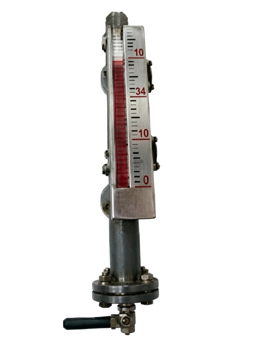
(Magnetic Level Indicator, known as MLI, commonly known as magnetic roller column / magnetic float liquid meter) LSD is based on the principles of the alignment of the Achmid floats with magnetic properties and is one of the most common visual liquids in industrial sites. It is linked to the detectable packaging by the principle of connection, and the floats rise and drop with the liquid level, using the magnetic coupling of the built-in magnet and the external flipboard (tricks) to achieve visual double colour displays.

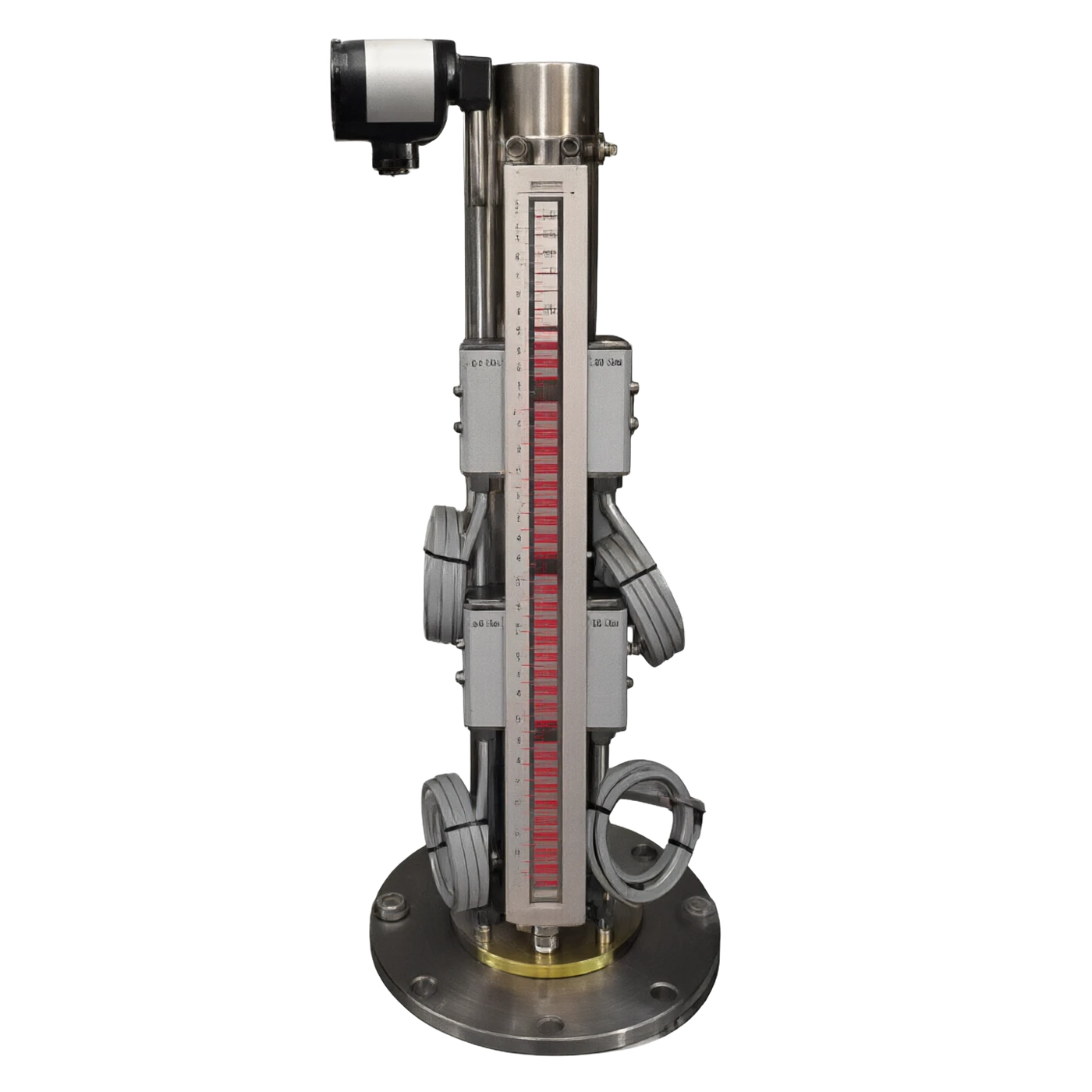
Advantages such as simple structures, high reliability, field visualization, power-free, high temperature and high pressure resistance, and the ability to load long-range transporters are widely applied to constant pressure and pressure containers in the petroleum, chemical, electrical, metallurgical, food and other industries. A combination of magnetic stretching or magnetic reed resistance long-range transporters can be combined with on-site visual and remote 4-20 MA + HART signal output, which is a liquid-level monitoring programme common to DCS/PLC systems.

This document will provide a systematic elaboration of the rationale, structure composition, comparison of strengths and weaknesses, application areas, technical parameters and selection guides, which will provide a reference for engineering design, equipment selection and on-site maintenance.

02

MEASUREMENT PRINCIPLE

Operating principle

2.1 Flow and connectivity principles

Connectors are formed by flanges or screws linked to the two receivers on and below the detectable container. According to the connection principle, the liquid level in the instrumental cavity remains consistent with the liquid level in the container. There is a dynamic b balance between the gravity G in the cavity and the mass float F: when the gravitational weight of the float is greater than that of the float, it sinks and floats back up. At the time of the fluid changes, the float remains at the balance position of the medium fluid surface, thus tracking the fluid changes in real time.

2.2. Magnetic coupling principles

The floats contain ring-shaped permagnetics (usually cylindrical radon N35-N52), distributed evenly along the floats ' perimeters, the N polar and S polar altercation magnetic fields.

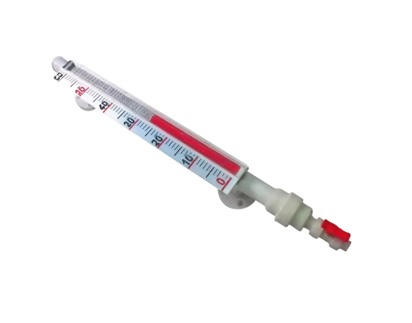
The plate (spread) on the outer side of the cavity consists of several separate units, each of which also contains a micro-peripherous or iron magnet. When the floater passes through a plate, the floater magnets and the flipper magnets generate a twist, which rotates the flipboard around its axis 180°, and the colour (usually red) is turned from a back-to-observer to a positive observer; The floater leaves and the plate remains in its current state, thus forming a visible "red-white divide", the red part being the area below the liquid surface and the white part above the liquid surface gas phase.

2.3. The principle of long transmission

The 4-20 MA+HART signal is exported by adding a remote transporter to the cavity. The common teleport programs are:

  1. 01

    Magnetic scalability long-distance

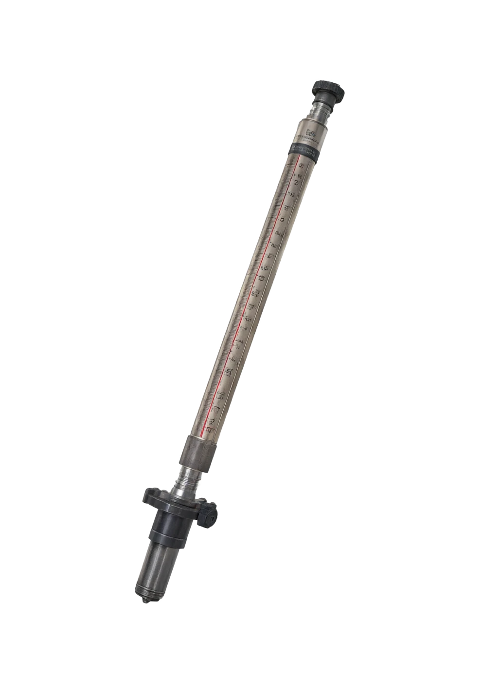
    (a) Magnetic scalable wave conductors installed on the external side of the cavity, and the reverse wave generated by the movement of the float magnets is detected and the ±0.5 mm level of precision is available;

  2. 02

    Magnetic reed resistance.

    Installation of several magnetic reed switches and precision electrical resistance in vitro, changes in electrical resistance values in float position, output of electrical voltage or current signals proportional to liquid level; magnetic switches (limit alarm): installation of frequent open/opening at specific locations outside cavity

Constantly closed magnetic reed switches to achieve high-level and low-level warning of liquids or pump control.

2.4 Liquid level display path

Page 3, page 4

Motion of work . Serial number / chainCross-reference
Serial numberLinkFunctional description
1Tested packagingsProvides raw liquid-level signals
2Up / Next Take over to FrankConnected cavity and packagings
3In vivo mediumConnect to container internal medium
4Float.Feel the surface position (floating balance)
5Floating magnetsGenerate a strong magnetic field.
6FlipboardDouble display of disks in flipping
7Remote Transmitrator (optional)Output 4-20 MA + HART
8Magnetic Switches (optional)High-Land-Lock Alert / Pump Control
03

PRODUCT STRUCTURE

Product structure

3.1 Typical structural composition

It consists of a cavity, floats, flipboard display components, process connections and an optional remote transfer device.

The structural components are as follows:

3.2 Typical structural diagram (text description)

Top plugs / exhaust valve (5) Main cavity (1) ⁇ flipboard (3) (inlined on the outside) ⁇ fluorinated (2) (inside the cavity) ⁇ Remote transvestite (7) ⁇ Bottom defilement valve (6) ⁇ Lower Frank (4) ⁇ Upper Frank (4) ⁇ Detachable packaging.

3.3 Structure Classification

Page 5, page 6

Body cavity (supervisor)

Main function: Connect to containers, provide floating up and down 31 common materials/ specifications: 6L / 304 / Haq alloy / titanium / PP / P

Float.

Main function: Feel liquid surface position (floating balance), internal constant 31-body 6 Common material / specification: L / Haze / titanium (inline N35-N52 magnet)

Flipboard

Main function: Double colour magnetic flip display unit (red / white or black / yellow) Usual material / specification: ABS / / / / 304 / 316L + aluminium flipboard

Go Up / Lower Frank

Main function: Linking to container take-over H Usual Materials / Specifications: G/T 20592 / ANSI / DIN

Top Block / Eros Valve

Main function: Sealed cavity, disabling internal gas, common mass / specification: 316L + PTFE seal

Bottom defecation valve

Main function: Cleaning of internal internal fluids / Erasing of materials commonly used / Specification: 316L + ball valve / needle valve

Remote Transmitrator (optional)

Main function: Convert liquid position to 4-20 MA + HART signal Usual material / Specification: Magnetic stretching / magnetic reed electrical resistance / magnetic switches

Shields (optional)

Main function: Protection of the plate from solar, ultraviolet, rainwater Usage / Specification: Transparency PVC / Polycarbonate + stainless steel framework

Hot-along kit (optional)

Main function: Prevent cryogenic medium crystallization or freezing Carbon Usual material / Specification: Steel / stainless steel pack (stealing / hot water cortex)

Ruler / Scale

Main function: On-site reading of precise liquid level height Common mass / Specification: stainless steel / Aluminium scale

By installation

Type: Side-packing (most commonly used) characterization: take over access to the side wall of the container through Frank

Type: Top-loading Description: Float inserted from top of the container, suitable for large storage tanks and underground tanks

By remote transmission

Type: Pure visual characterization: no remote transmission, live reading

Type: Magnetic reed resistance teleport characterization: low cost, general precision (±5 mm)

Type: Magnetic scalding remote characterization: high (±0.5 mm), fast response

Press the heat with the heat

Type: Unaccompanied heat

Type: Vapour kit type characterization: media crystallization, steamy corrosive heat

Type: Ether heat type characterization: medium requires constant temperature, electrotropical heating

By material

Type: Metal type characterization: 316L / Hax/ titanium, for high temperature and high pressure

04

TECHNICAL GUIDE

Analysis of strengths and weaknesses

4.1 Main advantages

Intuitive on-site

Specific: Double-chromatic flipping of the flipboard is clear, and the liquid position is readable without electricity, especially in case of powerlessness.

Simple and reliable structure

Specific: Inactable seals, no electronic components are exposed to the medium, MTBF can reach more than 100000 hours.

Apply medium wide from water

Specific: all industrial media can be addressed by replacing materials with oil to strong acid, organic solvents.

High temperature and pressure.

Specific: Metal type sustainable -40 ~ +450 °C, 0-10 MPa, up to 600 °C high temperature.

Install Simple

Specific: Only through flanges or threads will be required to connect to the container, and the installation base and the pipe will be low.

It's a combination of a long-range magnetic.

Specific: 4-20 MA + HART for extension or magnetic reed resistance long-distance output, easy access to DCS /

It's hot enough to keep it warm.

Specific: The application of a steam or electric heat kit can be expanded for crystal-friendly, visceral media.

But the police are at a low level.

Specific: High and low limit alerts or pump activation controls can be achieved by adding magnetic switches to the external cavity.

Maintenance waiver

Specific: No mechanical motion parts, no electronic components, contact media, almost no need for maintenance.

Disadvantages and use restrictions

Measurement of limited accuracy, pure vision

Response response proposal: ± 5 mm, long-range ± 1-5 mm, lower than pressure / differential variant ± 0.075%

Not applicable to sticky, crystal-friendly media

Response response suggested that floats may be packaged, carded or clogged, resulting in normal rise or fall of floats.

Not applicable to solid particles mediums containing large quantities

Response response recommendation: particulate matter is easily contained in the gap between the float and the cavity, resulting in a card delay.

Installation of space requires side-loading

Response response proposal: For the upper side wall of the container to be occupied, the top-mounted space is required, and the larger the range is required

Vertically Installed

Response response recommendation: Free rise and fall of floats in vertical direction is guaranteed and tilting installation can cause measurement errors or loss of float cards

Poor medium density adaptation

Response measures recommend that different density media need to replace floats of different weights and be re-selected when the medium density changes more.

Cleaning the board. Long-term.

Response measures: The use of a back-board surface may result in dust or stains, and the outdoor or dust scene is subject to regular cleaning or additional protection

We're weak in remote resistance to interference.

Response response measures suggest that magnetic reed resistance can cause signal fluctuations in the event of a strong magnetic field or vibration.

05

APPLICATIONS

Application area

Extensive use in the following industries and scenarios:

Page 7, page 8

Petroleum chemicals

Typical application scenarios: various constant pressure and pressure tanks, reactional Zeaks, distillation towers, feedstock tanks, intermediate tank liquid level measurements.

Gas and gas storage

Typical application scenarios: crude oil storage tanks, finished oil tanks, liquefied gas bed-hole tanks, liquid monitoring of well-filled gas fields.

Electricity

Typical application scenario: boiler packs, deoxygens, condensed water tanks, H / LHPLL.

Metal and metal

Typical application scenarios: acid scrubbers, cascading crystallizers, gas blend tanks, electro-saping fluids.

Environmental protection of water treatment

Monitoring of liquid levels of slurry ponds, white water towers, steam boilers, black tanks. Water-purification ponds, sediment tanks, filters, pharmacological tanks, sludge-condensed ponds.

Food and drink

Slurry ponds, white water towers, steam boilers, black-water tank liquid monitoring.

Pharmaceutical industry

Monitoring of liquid levels of slurry ponds, white water towers, steam boilers, black tanks.: Raw material tanks, fermentation tanks, disinfectant tanks, liquid levels (sanitary level optional).

Chemical new materials

Slurry ponds, white water towers, steam boilers, black-slurry liquid level monitoring: glue, dye, catalyst slurry, high viscosity fluid level (with heat-resistant crystal).

Building fire.

Monitoring of liquid levels in slurry ponds, white water towers, steam boilers, black tanks: monitoring of water levels in fire-fighting tanks, high-level water tanks, groundwater catchment pits.

06

TECHNICAL SPECIFICATIONS

Technical Parameter Table

The following parameters are generic technical indicators for typical magnetic roller tabler fluids, and the actual product parameters are based on the plant-out data sheet.

Page 9

Technical parameter table · Parameter item / Specification parameterCross-reference
Parameters itemSpecification parametersRemarks
Measuring span300 ~ 6000 mm (side-loading general) topIt's 12,000 mm, special 20,000.
Measurement precision (visual)±5 mm / ±10 mmThe width of the flipboard unit determines the accuracy level
Measurement precision (apogee)± 0.5 mm (magnetic scalding) / ± 5 mm (magnetized reed electrical resistance)It's different from the teleport program.
Medium density≥ 0.45 g/ cm³ (Standard Float) low densityType ≥ 0.35 g/ cm³ customised ≥ 0.25
Work pressure 0-1.0MPa (general)/ 0-4.0 MPa / 0-10 MPa (high pressure)(type) More stress will have to be customised
Process medium temperature40 °C ~ + 200 °C (general) highTemperature +450 °C, super-heat +600
Ambient temperature40 ℃ ~ +70 ℃The flipboard shows a low temperature effect.
Environmental humidity5% ~ 95% RHNo condensation
Ingress protectionIP54 / IP65 / IP67IP65 and above
Explosion protection markingExia ⅡC T6 Ga / Exd ⅡC T6 GbBased on GB/T 3836, only long-range needs
Process Connected DN20 / NN25 / NN50 Frank (HG/T / ANSI / DIN) Custom screws, hygiene level Tri-Clamp
Seal face formRF(bracket)/ FF(plain)/ MFM(deep)Based on process needs
Main material 316L/ 304 / Haps Alloy C / titanium / PP / PVC / PTFE lineIt's based on the medium's corrosivity.
Float material316L / HS / titanium / PTFEBe compatible with media
Flag materialABS / Cow/ 304 / 316L + Aluminium FlipboardOptional PC + aluminium flipboard for high temperature
Flipboard ColourRed/ White or Black/ YellowCustomise other colour combinations
Accompanying mode (optional)Vapour clamp / Hot water kit / Electric tropicsConfigure media when crystallized
Remote Transfer Out4-20 MA + HARTSelect Magnetic Zoom / Magnetic Reed Resist / Magnetic Open
Response time≤ 1 s (real-time visual)/ ≤ 0.5 s (magnetic stretching apogee)If the medium is highly volatile, it can be stopped.
Communications agreementsHART 7 / FF / PROFIBUS-PAOnly long-distance application
AuthenticationCE / ATEX / IECEx / NEPSI / CCCMeasurement CMC Authentication Optional
07

SELECTION GUIDE

Select Table

This section provides selected reference for five dimensions of "quantitative specification", "work pressure", "work temperature", "appliance scenario" and "process connection" to allow engineers to quickly locate models.

7.1 Selecting the format by Quantification Specification

7.2 Table of Type by Work Pressure

7.3 Table of type by working temperature

7.4 Table of types by application

Page 10

7.5 Process Connection Form Spacing

Page 11

Selective table · The quantum code / range of the rangeCross-reference
The quantum code.Measuring spanMountingTypical applications
RC-S1300 ~ 1000 mmSidewearSmall tanks, buffer tanks
RC-S21000 ~ 3000 mmSidewearMedium Reaction Pure, Storage Tank
RC-S33000 ~ 6000 mmSidewearLarge storage tanks, towers
RC-S46000 ~ 12000 mmSide / TopSuper-large storage tanks
RC-T11500 ~ 5000 mmTops.Large stand-by tanks
RC-T25000 ~ 12000 mmTops.Large storage tanks, underground tanks
Pressure codeOperating pressureTypical applications
PC-A0–1.0 MPa (average pressure)Constant pressure tanks, reservoirs
PC-B0–2.5 MPaGeneral pressure vessel
PC-C0–4.0 MPaCressor, Reaction Blank
PC-D0–6.4 MPaHigh pressure reaction pads
PC-E0–10 MPaHigh pressure boilers, cartons
PC-S≥ 10 MPaCustomized, special structural design required
Temperature CodeProcess medium temperatureTypical applications
TC-N40 ~ +80 ℃Temperature water, oil tanks
TC-M40 ~ +200 ℃Hot oil, medium temperature medium
TC-H40 ~ +450 ℃Steam, hot boiler packs
TC-U40 ~ +600 ℃Super-temperature melted salt, special processes
TC-L196 ~ +80 ℃LNG, LSD, deep cold medium
ApplicationsMedia FeaturesSuggested selection elements
Select Table . Constant pressure water / Tank / Constant temperature, low viscosityCross-reference
Water under constant pressure / TankTemperature, low viscosityRC-S1 / RC-S2 + 316L + Magnetic reed electrical resistance apogee
Boiler bag liquid levelHigh temperature, high pressure water saturation / steamPC-E + TC-H + Magnetic scalable abridged arcade + Double colour
Strong acid alkali tanksCorrosive.HSD/ titanium + PTFE liner + Magnetic scalability apocalyptics
Thin / High viscosityCyan, condensable.Vapour / electric heat + TC-M + large caliber French
LNG / LSD tankDeep cold - 196 °CTC-L+OZ +Special cryogenic seal
Health-grade storage tanksCIP/ SIP request316L polish + Tri-Clamp + Health-level Magnetic Scalp
Underground jars / wellfieldsLong-distance claims
The container is inside the wall.Could not close temporary folder: %sRC-T1 / RC-T2 Top-Cacket + Remote Display
Highwater tank / Firewater poolIt's warm, it's not corrosive.RC-S2 + IP67 Shield + Solar power transmission
Connection codeFormSuitable operating conditions
C-F25DN25 Frank (Standard for Side Load)General storage tanks
C-F50DN50 Frank (premise)Large stand-by tanks
C-F80DN80 FlangeLarge flows, high viscosity
C-N121/2 NPT inner screwSmall equipment, low pressure
C-G12G1/2 Inner screwEUROPE, MINORIARY EQUIPMENT
C-Tri50DN50 Tri-ClampHealth level, food / medicine
08

SELECTION GUIDE

Selection of guidance and attention

8.1 Selective Steps

8.2 Installation and use of attention

  1. 01

    The instrument verticality (recommended deviation ≤ 1 %) must be guaranteed, otherwise the float may be stuck.

  2. 02

    The distance of the upper/lower takeover of the French centre must be strictly consistent with the distance of the two French centres.

  3. 03

    The flange's tight bolts should be cross-cut, symmetrical and evenly increased to avoid single-sided receptors.

  4. 04

    The installation should be preceded by the cleaning of impurities and the transport of fillings in the cavity, and the validation of roller action should be carried out with a water test, if necessary.

  5. 05

    High temperature (with a dispersed heat sheet or shield) is recommended for media temperatures above 200 °C.

  6. 06

    The accompanying thermal medium should slowly open the valve to avoid the shock of the sudden heat on the glass flipboard.

  7. 07

    When the temperature of the medium is above 80 °C, the flip-board shield is recommended for the PC high temperature material.

  8. 08

    The outdoors should be equipped with rain masks to avoid the ageing of the UV-accelerated roller.

  9. 09

    The magnetic switch installation should avoid interference by a strong magnetic field and leave sufficient room for overhaul.

  10. 10

    The installation of hazardous sites must meet the requirements of the blast-proof level for the wiring and location.

  11. 11

    The inner cavity is to be cleaned and closed and the French interface sealed.

8.3 Maintenance and troubleshooting

Long-range transmission constant 4mA or 20mA long-range carrier failure/wire opener check for long-range power supply, retrace detection, replacement of carrier page 12 - End of document -

Selected guidance and attention . Steps / Key elementsCross-reference
StepsKey elements
Step 1 . Clearly measure objectsConfirms the name of the detected medium, density, viscosity, temperature, pressure, corrosivity, and whether it contains particles.
Step 2 Confirming the scaleSelect the side load/ top load and the quantification specification based on the geometric dimensions of the packaging and the required measurement range.
Step 3 Selected work pressureSelect PC-A ~ PC-S based on maximum working pressure of the container.
Step 4 . Select temperature levelSelect TC-N/TC-M/ TC-H/ TC-L based on the medium temperature.
Step 5 Selecting materialSelect the liner 316L/Hastium/PP/PVC/PTFE based on the corrosive properties of the medium.
Step 6 . Select the heat mixerCrystal-relative media need to be equipped with steam or electric heat packs.
Step 7 Selected apogeeSelect the magnetic stretch/ magnetic reed resistance/ magnetic switch based on precision and functional needs.
Step 8 . Select Process ConnectionSelect the flang/ screw/ sanitary level by the container interface.
Step 9 Installation and protectionThe protective shield, blast-proofing and protection levels are selected according to the environment on the ground.
Selection guidelines and attention · Common failures / Possible causesCross-reference
Common malfunctionsPossible causeSuggested measures
♪ Overboards unturned ♪Float carded dead / Magnetic steel failed / Flipping magnet failedDismantling cavity, checking floats and flipping magnets.
Red and white display errorFloats and flipboards diagonalRe-correct liquid level benchmark, check vertically installed
Transfer constant 4 ma or 20 mA. Remote transmission failure / wiring openCheck for telepower, check for circuits, replace transducers
Selecting guide and attention · Remote transmission does not match visual / / / / Media density changesCross-reference
The distance transfer is not consistent with the visual.Zero-point drift / Media density changeRemark, modify the medium density
Media leakFranc seal is disabled / Float ruptureReplace seals / floats, secure Frank
The colour of the flipboard is lighter.Long-term UV irradiation / medium chemical erosionPut in a shield and replace the flipboard.
Floating-up card delayCrushing / crystal / particle accumulationDismantling cavity clean-up, with heating if necessary