PRODUCT TECHNOLOGY

Pressure autochecker

Operating principle

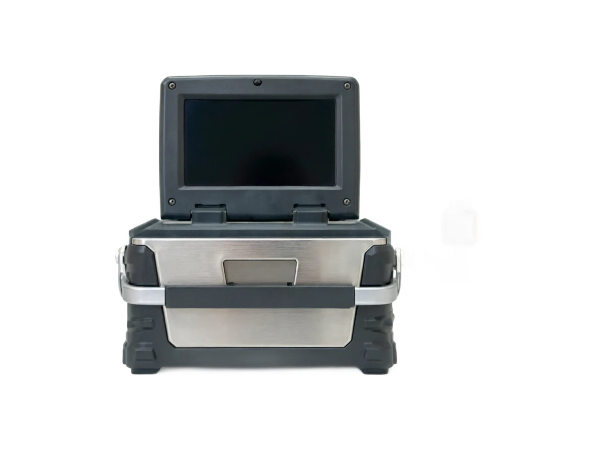
The pressure autochecker.

The working method is "pressure source + standard unit + control + ratio to " Quadrelation structure: pressure source module produces precise and stable pressure (gases or liquids) by command of the upper engine; (a) Standard unit modules for real-time monitoring of pressure truths (scaling of piston pressureometers + float position, or DPC readings of digital pressure meters); (a) The control module uses PID algorithms to dynamically adjust pressure source server valves to allow for rapid stabilization of pressure to target values; Multi-channel scanner valves are then switched to the filter instrument to synchronized collection with the standard instrument, and the error is measured by the upper machine software. The system automatically completes the test by following the JJG protocol's " point up + point down + two-way process" and completes the report of the output of raw data, error curves, back-routing errors, repetition, uncertainty assessment, etc. The pressure source is the auto-check device's core.

  1. 01

    100kPa ~ 7MPa, stability ±0.005%FS; 2 Oil Source (hydropumps): Use pure hydraulic fluid (purified hydraulic fluid) ISOVG32/46 ) or aviation oil as media, commonly in the form of manual/electrically high pressure pumps, stevell pumps, booster pumps, etc., typical pressure range

  2. 02

    Require: original data not tampered with storage (including operator ' s electronic signature, Hashi verification); q. Quantities trace chain automatic record (standard device certificate number)

  3. 03

    Time stamp. Superior measurer.

  4. 04

    1 . Parameter input . Checkpoint 5 / 10 + up and down order + channel allocation . Test task list —

Pressure autovalidation device selection support

Provide survey missions, media and installation conditions and obtain product configuration advice.

Contact us
· Technical Note

TECHNOLOGY & APPLICATION

Understand the principles, the exact selection.

From measurement principles to field applications, the technical features and selection elements of the pressure autovalidation device are understood.

01

TECHNICAL GUIDE

Overview

(Automatic Pressure Infrastructure System, APCS) is an integrated device for automating/calibrating pressure gauges such as pressure transmitters, pressure switches, pressure meters, differential transmitters, vacuum meters, etc. It integrates precision pressure sources, high-precision standard pressure sensors (or piston pressure meters), multichannel data acquisition systems, industrial control units (PLC/MCU), specialized validation software with traceability databases into one device or cabinet, and sets the national measurement test protocol (JJG 882-2004/JJG 49-2013/JJJG 875-2005) or the enterprise ' s custom-defined programme for automatic lifting, pressure, pressure relief, data collection, error calculation, qualification, certificate printing and data archiving, with efficiencies of 5-10 times the traditional manual validation.

1.1 Product positioning and value

The core value lies in upgrading the traditional pressure validation model of "manual reading, manual recording, Excel computing" to an automated full-process model of "automatic pressurization, automatic collection, automatic computing, automated certification", to achieve the four main objectives of "digitization, traceability, reduction efficiency, transparency of compliance" in measuring and measuring the measurement. Compared to the traditional "HWP+Standard Table + Notebook" programme, the ATMs have significant advantages such as high accuracy, efficiency, small human error, data traceability, batch validation, remote auditing, etc., and have become standard equipment for statutory and enterprise measurement laboratories under the JJG system.

1.2 Brief history of technological evolution

Four main stages were passed.

① 1970 (a) The era of pure manual: manual piston pump + glass tube U-type pressureometers, depending on eye reading; The 1980s digital pressurer age: handheld digital pressureometer (DPM) replaced glass tube fluid meters, increasing to ±0.05% FS, but still single point manual collection; ③ 1990 ~ 2000 (a) The semi-automatic age: PC + standard pressureometer + data acquisition card + validation software (e.g. Fluke/CalMet/Prosures series) to automatically capture and calculate data, but the pressure and pressure still need to be manual; The 2010s to date: Integrated Server Pressure Pump + Multi-channel Scan Valve + Pistol Standard (or DPC) + Work Control PC + Database is connected to LIMS to achieve full process unserviceable and electronic certificates. ISO 17025 / JJF 1069 for the same period requires that all measurement activities be retroactive, and the electronic records and electronic signatures of automated verification devices become key capabilities for compliance.

1.3 Comparative positioning with traditional manual validation

Traditional manual verification

Manual piston pump (or hand-shake pressure pump) manual pressurization to the point of check manual reading of the checklist and standard forms manual recording of manual computation errors on paper manual certification manual certification certificate Automatic verification process: The upper-spaced command ⁇ PLC control server pump automatically presses to target value ⁇ Multi-channel scanning valve switch to ⁇ System ⁇ System ⁇ Systems ⁇ Systems calculates error, back-curve error, repeatance ⁇ Accessually determines the validity of electronic signature ⁇ Data archive ⁇ Reports/certs are automatically generated. From the perspective of measurement compliance, the automated verification device will store all raw data, pressure curves, time stamp, operator electronic signatures, meeting all requirements of ISO 17025 and FDA 21 CFR Part 11 for electronic records and electronic signatures.

Table 1-1 Global mainstream plant and representative model for pressure autovalidation devices

General description · Serial number / BrandCross-reference
Serial numberBrandTypical ModelMain pressure rangeCharacteristic positioning
1Fluke.2271A / 8270A / E-DWTMicropressure ~70 MPaIndustrial-grade hydraulic pressure double-module
General description · Serial number / BrandCross-reference
Serial numberBrandTypical ModelMain pressure rangeCharacteristic positioning
2GE Sensing / DruckPACE1000 / DPI 620 GenIIAir pressure 0~21 MPaMultifunctional Handheld + Auto-Back
3BeamexMC6 / MCS200 / PGMC100 kPa~100 MPaPortable + live bus integration
4Wika (Wika)CPC8000 / CPC60000.1~70 MPaHydraulic high-precision piston type
5Ametek / MensorCPC3000 / CPC6000Air pressure 0~7 MPaHigh precision quartz crystal pressureometer
6DH-BudenbergCPG2500 / 5800DXHydraulic 0~100 MPaPistol pressure gauge old company.
7Transmille (UK)9000 Series Pressure ModuleMedium pressure full rangeModularization, module interpolation
8Nutech2025P / 2015PAir pressure 0~7 MPaThe Metrics Level is fully automatic
9National: ConstConST811 / ConST620Pressure - 100 ~ 700 kPaMainstream in national production
10National: Long Peak / Taeway / HuaigenCST/ TF/HY seriesFull pressure range.Middle market / Domesticization
02

MEASUREMENT PRINCIPLE

Operating principle

The working method is "pressure source + standard unit + control + ratio to " Quadrelation structure: pressure source module produces precise and stable pressure (gases or liquids) by command of the upper engine; (a) Standard unit modules for real-time monitoring of pressure truths (scaling of piston pressureometers + float position, or DPC readings of digital pressure meters); (a) The control module uses PID algorithms to dynamically adjust pressure source server valves to allow for rapid stabilization of pressure to target values; Multi-channel scanner valves are then switched to the filter instrument to synchronized collection with the standard instrument, and the error is measured by the upper machine software. The system automatically completes the test by following the JJG protocol's " point up + point down + two-way process" and completes the report of the output of raw data, error curves, back-routing errors, repetition, uncertainty assessment, etc.

2.1 Pressure sources (gas/ oil sources/ pistons)

Pressure sources are core implementing agencies for automatic verification devices, divided into three categories by type of medium: gas source (pressure pump): use of compressed air or high-purity nitrogen gas as a medium, commonly in the form of server-driven piston pumps, electromagnetic valve switching prepressure cylinders, amplifiable pressure controllers, etc., typical pressure ranges

  1. 01

    100kPa ~ 7MPa, stability ±0.005%FS; 2 Oil Source (hydropumps): Use pure hydraulic fluid (purified hydraulic fluid) ISOVG32/46 ) or aviation oil as media, commonly in the form of manual/electrically high pressure pumps, stevell pumps, booster pumps, etc., typical pressure range

0 ~ 250 MPa, stability ±0.01%FS, applicable to high pressure meters and transmitters; 3 piston pressure source: Exact pressure based on pascotal principles and power balance code, piston area and code mass determine pressure values, which are the core vector of the national measurement baseline and are accurate enough ±0.005% ~±0.02%FS is the "highest precision standard" of the auto-validation device.

2.2 Standard pressure sensors (digital pressureometers / piston pressureometers)

Standard pressure sensors are "Measurements" of pressure truths and are divided into two categories according to the working method: a digital pressureometer (DPC, DigitalPressureCalibrator/Controller): high-precision quartz crystallized pressure sensors or silica pressure resistance sensors to measure accuracy ±0.01%FS ~ ±0.05%FS, with a flexible change of range (multimodule design), in conjunction with 24 bit ADC and DSP digital compensation, and output standard pressure genuines; 2 piston pressureometers (DWT, DeadWeightTester): Composed of precision piston-cylinder components and ciphers, using the principle of "scaling gravitational piston effective area = pressure" to generate baseline pressure with the highest accuracy ±0.005%FS This is the core of national measurement benchmarks and delivery standards, with the disadvantage that pressure is slow and not suitable for mass verification. Modern high-end autovalidation devices are usually integrated into "DPC + DWT Double Standard" , DWT is used to trace volume, and DPC is used for routine validation.

2.3 Multi-channel scanning valves and signal acquisition

Multi-channel scanning valves (Multi-channelScanner) are the "toggle hub" for auto-validation devices, which are responsible for connecting 1 standard pressure sources sequentially to 4 ~ 32's checklists, achieving "one pair of multiple" batch verifications. Common type: 1 electromagnetic valve matrix (ATM) 4 / 8 / 16 ♪ I'll be back in a minute ♪ ≤ 100 ms, leakage rate ≤ 10 Pa· m³/s ; 2 Aerodynamic-driven spin valve core, response time ≤ 500 ms, leakage rate ≤ 10¹ Pa· m³/s ; More than 3-channel air-breath balance that sustains multiple independent pressures and response times ≤1 s。 The signal capture module is collecting all the detected telecommunications simultaneously. 4 - 20mA / HART / 0 - 10 V / RS-485 ), A/D resolution 24 Bit, sampling rate 1 ~ 10 Hz, closely aligned with standard pressure values by time stamp.

2.4 PID Control and Pressure Stability

PID control algorithms are key to the rapid stabilization of pressure sources to target values. (a) The system uses a serial PID: 1 main circuit to calculate the control based on deviations between pressure setting values and standard instrument measurements; 2 secondary circuits adjust the opening of the valve to the feedback of the location of the server valve; 3 Add pre-feed control (pre-compensation based on pressure change rate) and death zone compensation, resulting in pressure reaching ±0.005%FS Time of stability ≤ 5 s, steady-state fluctuations ±0.002%FS 。 Pressure stability is a fundamental guarantee of accuracy - if the source of pressure itself is unstable, the standard instrument of high accuracy is meaningless.

2.5 Data processing versus automatic matching algorithms

Software module executes 5 calculations immediately after each checkpoint collection is completed

(a) 1 is checked to indicate a value error = output real - standard pressure value (consolidated by scale); 2 return error = pressure reading - pressure relief reading (assessing delay characteristics); 3 Repeated = 3 Standard deviations in secondary cycle data (assessment of random errors); Linear error = maximum deviation between the actual feature curve and the proposed line; 5 General uncertainty assessment: u_c = ⁇ (u_ standard 2 + u_ repeat 2 + u_ resolution 2 + u_ temperature 2 + u _ point 2). The certification certificate with an electronic signature is automatically determined to be qualified/defeating on the basis of a judgement such as JJG882-2004/JJG49-2013.

2.6 Data traceability and electronic certificates

Modern automated verification devices are based on the national benchmark ISO 17025 and JJF1069; Auto-generated validation/correction certificates (PDF + electronic signatures) in JJG format; Support for a two-way data exchange with LIMS; FDA21CFRPart11 requirements for electronic records and electronic signatures are met. These capabilities have enabled the automated verification devices to be upgraded from "tools" to "measure compliance systems".

Table 2-1 Pressure autochecker 8 Step workflow

  1. 01

    Requirements met

    Original data cannot be tampered with for storage (including electronic signature of operator, Hashi verification); q. Quantities trace chain automatic records (standard device certificate number)

  2. 02

    + →

  3. 03

    Time stamp. Superior measurer.

  4. 04

    + →

Motion of work . Step / Signal phaseCross-reference
StepsSignal phaseMain processingOutput FormPrecision range
1Parameter InputCheckpoint 5/10 + Pressure-down order + Channel AllocationTest Task Sheet—
2Pressure source pressurizesServer pump / code load / piston rotationUp the pressure curve±0.01%FS
3PID PressureMaster + Deputy Two-way + front-pushStabilized pressure ± 0.005% FS±0.005%FS
4Scan valve switchMulti-channel electromagnetic valves or aerodynamic valvesChecked for accessLeak. ≤ 10 Pa·m³/s
5Standard readerDPC 24 bit ADC / DWT code balancePressure is real.±0.005~±0.05%FS
6Reads reviewed4-20mA / HART / 0-10V / RS-485Telecommunications are real.24 bit / 0.01% FS
7Error calculationLogical/return/duplication/linear/uncertaintyError reportAuto-determination
8Certificate ArchiveElectronic signature + database + LIMS NetworkValidation/correction certificateISO 17025 Compliance
03

PRODUCT STRUCTURE

Product structure

Using the "hardware + software + build" three-tiered architecture, the hardware layer consists of 12 core components (Camber + Pressure Source + Standarder + Multichannel Scanner + Control + Signal Picker + Touch screen + Power + Communications Interface + Safety valve + Gas tank/ oil tank + Kit) and the software layer consists of Test Management Software (test Management) + ErrorConnector + Pipeline (Tubing). The 4 type of structure can be divided by the degree of integration: portable, desktop, counter, distributed.

Table 3-1 Pressure auto-checking devices 12 Widgets structure table

Engineering + Certificate Generation Modules

Fixture+

Database + QuickPlugin

Airbox / Car

Main function: Load all components + Move Key materials/processes: ⁇ / stainless steel / silent wheel Fault mode: deformation, card block

Pressure sources (gas/oil pumps)

Main function: Provide precise and manageable pressure Key material/process: Server + Pump Fault mode: wear, leak

Standard pressure sensors

Main function: Pressure truth measurement Key material/process: Stone crystal / Silicon pressure resistance Fault mode: drift, zero offset

Pistol pressureometer component

Main function: Maximum accuracy traceability standard Key material/process: Pistol-Cylinder + Shape + Fault mode: Pistol wear, tank deformation

Multi-channel scanning valve

Main function: A multi-channel switch Key material/process: EMP matrix / Aerodynamic valve Fault mode: seal failure, valve core card block

PLC / controller

Main function: PID control + time sequence logic Key material/process: Siemens S7 / Mitsubishi FX failure mode: program flight, reset

Signal pick-up card

Main function: Multichannel telecommunications collection Key material/process: 24 bit ADC + HART Modem failure mode: channel string disturbance, noise

Work Control PC / Touch Screen

Main function: Upper aircraft interface Key material/process: i5/15 Handler + 21 " LCD failure mode: Hard disk damage, touch screen failure

Gas tank / Tank

Main function: Stable pressure source + Buffer Key material/process: 316L stainless steel + O Circle Fault mode: Leak, corrosive

Safety valve / blast fragments

Main function: Overpressure protection Key material/process: spring + film rupture mode: spring fatigue, film failure

Communications interface module

Main function: Networking of the upper-placer with external systems Key material/process: RS-485 / USB / Ethernet / GPIB failure mode: interface failure, communication error

Plugins and pipes

Main function: Connection to the checkpoint Key material/process: Fast plug + stainless steel pipe Fault mode: leak, jam

Circuit/airway module

Air/oil road module

Main component: EMP + pressure valve + tank Key function: steady + pressure + security protection Performance indicator: pressure fluctuations ⁇ ±0.005% FS

Signal capture module

Main component: 24 bit ADC+ signal reconciliation Key function: high accuracy telecommunications collection Performance indicator: sampling rate 10 Hz / commopression 100 dB

Control module (PLC/ MMU)

Main widget: PLC + PID controller Key function: Time series + PID + Security locking indicator: PID cycle ≤ 10 ms / Security Phase SIL 2

Power and isolation

Main component: DC-DC + EMC Filter Key function: Power supply for PLC + pick-up card Performance indicator: 24 VDC ±5%/ Separate 1500 V

Communications module

Main Component: RS-485 + Ethernet + GPIB Key Functions: Networking with Upper and LIMS Performance Indicators: Communication Rate ≥ 115.2 kbps

Upboard software

Main component: Test Mgmt + Error Engineering + DB Key function: Test process organization and calculation Performance indicator: Support for JJG 882/JIF 1069 Full program

Construction

Portable (Handheld)

Exterior: Within handheld 4 kg, containing batteries + pumps Integration: single channel semi-automatic Typical application: on-site inspection, temporary verification

Desktop (Benchtop)

Exterior feature: Desktop size 600 x 500 x 300 mm, touch screen integration: single channel or 4 channel full automatic application: laboratory and small station check

Console

PHYSICAL DIMENSION: 19" SETAC: 1200x600x1800mm Isolation: 8-16 channel full automatic application: Measurement and control agency/ instrument manufacturing plant

Distribution

Exterior features: Multiple stand-alone modules interconnected through bus Isolation: 16 ~ 128 Channel Large scale Typical applications: large production lines / mass verification of plant

04

TECHNICAL GUIDE

Advantages and disadvantages

As a modern measurement infrastructure, there is a revolutionary advantage over traditional manual validation, but there are also high investment, operational complexity and inherent deficiencies in maintenance requirements, which need to be weighed against the selection of projects.

4.1 Main advantages (8 grand)

4.1 Main advantages (8 grand)

Validation efficiency

Detailed: Batch verification 8 ~ 32 A meter, full automated process less time-consuming than manual 70% ~90%

Human error small

Detailed: Elimination of errors in human reading, errors in handwritten recording, errors in computation, significant increase in repetition

Data traceability

Detailed: Raw data, time stamp, electronic signature of operator solidified to meet ISO 17025 and FDA 21 CFR Part 11

Volume trace exact

Detailed: Standard tape measurement certificate, automated write-in of the trace chain to avoid human omission

Automation statements

Detail: Auto-generated JJG format calibration/correction certificate with electronic signature, directly sent by PDF or LIMS archive

Batch consistency

Detailed: The same type of instrument is subject to mass verification, and the timing of the check points, pressure velocity, pressure time and heights are consistent to facilitate quality control

Remote audit

Detailed information: Remote access to databases is supported and audit staff are not required to be present to verify the records

Reducing human costs

Detailed: 50% 80% reduction in metering staff, multiple equipment managed by one person, high return on long-term investments (ROI 3-5 years)

Disadvantages and use restrictions

High investment in equipment

Detailed: 50 ~ 3000000, portable 5 ~ 300000, high SME threshold

Operation complexity high

Detailed description: Professional metrology engineers need to be trained for 1 to 2 weeks, with beginners having difficulty in getting the job done

Maintenance requirements are high

Details: Standard machines need to be inspected annually + piston pressureometer washing + scanned valve seals replacement, annual maintenance 2 ~ 100000

Environmental requirements are stringent

Detailed: Heat lab (20 ± 2 °C) + dust protection + vibration, unsatisfied in normal workshop environment

Media Compatibility Limit

Detailed: Gas sources cannot be mixed with oil sources, and the same equipment usually covers only one medium and replaces complex media

Specialized software binding

Detailed: Different manufacturers are not universal, some of them lock in data formats, and replacement of the plant requires retraining and system re-engineering

Fault clearance difficulties

Detailed description: High convergence of gas/oil/wire/software, difficulty of on-site maintenance in case of failure requiring technical support from the plant

05

APPLICATIONS

Application area

The main service is in the two areas of "National Statutory Measurement System" and "Industrial User Measurement System", covering 14 typical industries and 5 large user groups. The requirements for pressure ranges, accuracy levels, automation levels and media types vary significantly from application scenarios, and the appropriate product specifications need to be selected according to the specific conditions of the work.

Table 5-1 Pressure autovalidation devices 14 Large typical application scenario 5-2 Pressure autovalidation devices 5 Large user group selection matrix

National Institute of Measurement and Measurement

Typical calibration scenario: Quantification benchmark, arbitration determination Pressure range: Micropressure ~250 MPa Key Requirements: Maximum Precision ±0.005% FS

Third-party control units

Typical calibration scenario: petrochemical, third-party inspection of electrical instrumentation Test Pressure range: full pressure range Critical requirement: ISO 17025

Petrochemicals and chemical works

Typical verified scene: Reaction Zoom, distillation tower, tank pressure gauge pressure range: 0~70 MPa Key requirements: blast protection + media compatibility

Electricity and energy

Typical calibration scenario: boiler steam, steam engine, water pressure: 0~35 MPa Critical requirements: high temperature, high vibration resistance

Long run of gas.

Typical validation scene: pipelines, tanks, CNG/LNG station Pressure range: 0~25 MPa Key requirements: high accuracy + remote data

Metal and metal

Typical calibration scene: furnace, transcrib, cast, roller hydraulic pressure range: 0~100 MPa Key requirement: anti-oil + long life

Aerospace

Typical calibration scene: fuel system, hydraulic system, compartment pressure differential: 100 kPa~70 MPa key requirement: high accuracy + high reliability

Defence Forces workers

Typical verification scene: weapons tests, ships, tank fluids Pressure range: full pressure range Critical requirements: confidentiality compliance + national production

Instrument manufacturing plant

Typical validation scene: plant-based, mass-production line-based test Pressure range: full pressure range Critical requirements: efficiency + multiple channels

Medical equipment

Typical calibration scene: Sphygmomanometer, fluid pump, respiratory pressure Pressure range: 50~ + 300 kPa Critical requirements: Health level + clinical compliance

Food and drink

Typical verified scene: CIP Purge, Baccalaurecism, Filling Pressure: 100 kPa~2 MPa Critical Requirements: IP69K + EHEDG

Pharmaceutical industry

Typical verified scenes: fermentation tanks, fungi, clean areas Pressure range: 50 ~ +500 kPa Key requirements: Health level + GMP

Semiconductor and Panel

Typical calibration scene: Vacuum cavity, corrosive, CVD pressure range: 10 Pa~500 kPa Key requirements: super-high vacuum + particle control

Environment and meteorology

Typical calibration scenario: barometers, atmospheric pressure measurements Pressure range: 10 hPa ~110 kPa Critical requirements: climate compensation + long-term stability

User group

Precision requires, number of channels, pressure range, preferred type series.

National Institute of Measurement and Measurement

±0.005% FS 1 ~ 4 channel Full pressure range Fluke E-DWT/ Plugin type

Third-party institutions

±0.02% FS 4 ~ 8 Channels 0 ~ 70 MPa Wika CPC8000 / Beamex MC6

Petrochemicals

±0.05% FS 8 ~ 16 Channel ~ 0 25 MPa Const ConST811/ National Production Series

Electricity enterprise

±0.05% FS 4 ~ 8 Channel ~ 0 35 MPa DPI 620 / ConST620

Instrument manufacturing plant

±0.05% FS 16 ~ 32 channel by Nutech 2025 P/ Distribution

06

TECHNICAL SPECIFICATIONS

Technical Parameter Table

Table 6 - 1 Pressure autochecker 25 Table of the entire machine parameters 6 - 2 Pressure autochecker 6 Class Standardr Comparison Table 6 - 3 Pressure autochecker 6 Category pressure source comparison

Technical parameter table . Serial number / parameter itemCross-reference
Serial numberParameter ItemSpecificationsTypical values/ranges
1Pressure range (air pressure)Maximum pressure of the gas medium100 kPa ~ 7 MPa (common)/ 21 MPa (high pressure)
2Pressure range (hydroclaves)Liquid media pressure limit0~70 MPa / 0~250 MPa (high pressure hydraulic)
3Micropressure RangeSmall pressure (discretion) range±1 kPa / ±10 kPa / ±100 kPa
4Media TypeGases or liquidsAir / N / hydraulic fluid / water / aviation oil / fluorinated fluid
5Standard PrecisionMaximum measure precision±0.005%FS / ±0.01%FS / ±0.02%FS / ±0.05%FS
6Pressure stabilitySteady-state volatility±0.005% FS (PID control)
7Pressure ResolutionMinimum pressure change step0.001 kPa / 0.01 kPa / 0.1 kPa
8Up speedMaximum pressure rate10 kPa/s ~ 1 MPa/s (Automated Swap by Scale)
9Steady the pressure time.Time taken to reach target value≤ 5 s (typical)
10Number of channelsSynchronization of the meter1 / 4 / 8 / 16 / 32 Channel
11Scan valve response timeChannel Switch Time≤ 100 ms (Electromagnetic Valves) / ≤ 500 ms (Aerodynamic Valves)
12Scan valve leakage rateInter-channel sealing performance≤ 10 Pa. m³/s (He mass spectroscopy leak)
13Collect precision24 bit ADC quantitative error± 0.002% FS (linearity)
14Sample RateCollect points per second1 ~10 Hz truncable
15Type of telecommunicationsChecked to input signal4-20mA / HART / 0-10V / RS-485 / Modbus
16Communication interfaceThe top-off and the outside interfaceRS-232 / RS-485 / USB / Ethernet / GPIB / IEEE 1588
17Data StorageLocal storage of raw data≥ 10000 Group Test Record / ≥ 1 TB Hard Disk
18Certificate FormatVerify Certificate Output FormatPDF+E-signature +JJG Standard Format
19Ambient temperatureWorking environment temperature20 ± 2 ℃ (laboratory level) / 0 ~ +40 ℃ (industrial level)
20Environmental humidityWork environment humidity30% ~ 80% RH (without condensation)
21Electricity voltageWork powerAC 220V 50Hz / AC 110V 60Hz (by region)
22Rating PowerMaximum power of the whole machine500 W ~ 3 kW (includes pressure sources)
23WeightNet heavy equipment5 kg (portable) ~ 300 kg (closer)
24Overall dimensionsWhole machine sizePort 400 x 300 x 200 mm/ counter 1200 x 600 x 1800 mm
25Measuring complianceCompliance with standards and regulationsJJG 882 / JJG 49 / JJG 875 / ISO 17025 / JJF 1069
Technical Parameter Table . Standard Device Type / ModularCross-reference
Standard Device TypeOperating principleAccuracy classPressure rangeTypical applications
Digital Pressure Sheets DPCStone-in-crystal/ Silicon Pressure±0.01%FS~±0.05%F S100 kPa~70 MPaDaily verification/ portable equipment
Pistol Pressureometer DWTScramble / Pistol Area±0.005%FS~±0.02% FS10 kPa~250 MPaNational baseline / volume traceability
Mercury cylinder pressureometersMercury column fluid level difference±0.05%FS~±0.1%FS10 kPa~300 kPaMicropressure / Vacuum Measurement
Cosmetics of bellowsBlanket offset + spring±0.1%FS~±0.5%FS10 kPa~1 MPaDifference / Low Pressure Validation
Liquid column balanceWater column height is low±0.02%FS~±0.05%F SMicropressure ~ 100 kPaMicropressure benchmark / Weather
Gas piston pressureometerGas pistons + code±0.01%FS~±0.05%F S10 kPa~10 MPaAir pressure high accuracy benchmark
Technical Parameter Table . Pressure Source Type / MediaCross-reference
Pressure source typeMediaPressure rangeStabilityTypical applications
Server air pumpAir/N100 kPa~7 MPa±0.005%FSAuto-validation of Mainstreams
EMPs switch cylinders.Prepressure cylinders0~21 MPa±0.02%FSWith high pressure.
Server hydraulic pumpsHydraulic fluid0~70 MPa±0.01%FSValidation of pressure hydraulics
Pressure booster pumpHydraulic fluid0~250 MPa±0.02%FSHigh pressure hydraulic verification
Pistol Pressure source DWTOil / Gas10 kPa~250 MPa±0.005%FSNational benchmarks
Manual pressurized pumpOil / Gas0~70 MPa±0.05%FSPortable / Semi-automatic
MediaPressure rangeSealed materialsTypical industriesAttention
Air100 kPa~7 MPaNBR / FKM / EPDMGeneral IndustryWater de-oil (< 5 ppm)
Nitrogen N100 kPa~21 MPaNBR / FKM / MetalHigh purity, protection against oxidationInert gases are not contaminated
Hydraulic fluid VG320~70 MPaFKM / PTFE / MetalGeneral hydraulic pressureSaludity stabilization temperature compensation
Air oil Skydrol0~35 MPaEPDM / FKM / PTFEAerospaceIt's acidic, it needs PTFE seals.
Pure water.Micropressure ~1 MPaEPDM / ceramicsFood / MedicinePrevention of biobacterial pollution
Fluorinated liquidsMicropressure ~5 MPaPTFE / MetalSemiconductor superpurityParticle control < 0.1 ppm
07

SELECTION GUIDE

Select Table

Tables selected by pressure range, accuracy level, medium type, automation level 4 Each dimension is given separately. 6 / 5 / 5 / 5 A line comparison sheet allows engineering designers to systematically select according to specific conditions.

Table 7-1 Selected pressure range for pressure autochecking devices (6 rows)

±0.005% FS gas piston DWT national benchmark/arbitration certificate FlukeE-DWT/ Ruska2465 ⁇ 0.01% FS digital pressureometer DPC provincial measurement/critical project level I measurement certificate ±0.02% FS high accuracy DPC enterprise metering certificate table 7 - 4 table (5 row)

  1. 01

    ±0.05%FS ±0.1%FS

  2. 02

    Standard DPC Universal DPC

  3. 03

    Workshop-level verification, site inspection.

  4. 04

    - The exit certificate. - The inspection log.

  5. 05

    CONST811/DPI620 Fluke750P/Package

Selecting Table . Pressure / MediaCross-reference
Pressure rangeMediaPrecision SelectionTypical applicationsRepresenting products
Micropressure ±10 kPaGases±0.05%FSAtmospheric pressure / micro differential pressureMensor CPG2500 / ConST620
Low pressure 0-7 MPaGases±0.01%FSIndustrial generic pressureFluke 2271A / DPI 620
Middle press 0~35 MPaGas / Oil±0.02%FSGas / petrochemical / electricityBeamex MC6 / Wika CPC8000
High pressure 0~70 MPaHydraulic fluid±0.02%FSHigh pressure hydraulic / aviationWika CPC8000 / DH 5800DX
Superhigh pressure 0~250 MPaHydraulic fluid±0.05%FSDefense / High Pressure TestDH-Budenberg 5800DX / Homemade
Vacuum 10 Pa~100 kPaGases±0.5%FSSemiconductor / Vacuum MeasurementInficon / Lebow
Accuracy classStandard Device TypeTypical applicationsCertificate PurposeRepresenting products
±0.005%FSGas piston DWTNational benchmarks / arbitrationNational benchmark certificatesFluke E-DWT / Ruska 2465
±0.01%FSDigital Pressure Sheets DPCProvincial measurement/critical projectsCertificate of first-degree measurementMensor CPG2500 / GE PACE1000
±0.02%FSHigh Precision DPCEnterprise Measurement RoomCertificate of Level MeasurementWika CPC8000 / Beamex MC6
±0.05%FSStandard DPCWorkshop-level verificationCertificate of exitConST811 / DPI 620
±0.1%FSGeneric DPCOn-site inspectionInspection recordsFluke 750P / Portable
Media TypePressure sourceSealTypical industriesSelection Recommendations
Air / NServer air pumpNBR / FKMGeneral IndustryMainstream, high value for money
Hydraulic fluidPumps, piston hydraulic pumpsFKM / PTFEHigh pressure hydraulic / metallurgicalHigh Pressurized Preferred
Aviation oilPump + PTFE SealPTFE / MetalAerospaceSpecific aviation oil XL specification required
Pure water.Ceramic Pumps / EPDM SealedEPDM / ceramicsFood / MedicineHealth level requirements
Fluorinated liquidsMetal pump + Total metal sealMetal / KalrezSemiconductor / SuperpurifiedParticle control
Selective table · Automation level / Manual Intervention PointCross-reference
Level of automationManual Intervention PointNumber of channelsTypical sceneRepresenting products
Manual (portable)Full-time manual1On-site inspection/ emergency responseFluke 750P / DPI 610
Semi-automaticOnly pressure needs manual1~4Small batch of laboratoryBeamex MC6 / Wika CPH7000
Full Auto DesktopOnly manual.4~8Regular inspection of the institutionCONST811 / Nationally produced series
All-auto cabinets.Only manual.8~16Measurement agency backboneFluke 2271A / Nutech 2025P
No one's watching.All Automatic16~128Online verification of production linesDistributed + Mechanical Program
08

SELECTION GUIDE

Selection Guide

8.1 10 Step-style process

8.3 Pressure autochecker 10-line selected decision tree

This summary covers all key technical elements of the pressure autochecker system, from the rationale, structure, application to the project selection. The actual selection should also be based on a detailed demonstration of the latest product manual for the manufacturer, measurement inspection protocols and the enterprise-specific performance, and the final programme evaluation by a professional metrology engineer.

Selection Guide · Steps / SelectionCross-reference
StepsSelect contentKey decision-making points
1Confirm the type of instrument being checkedPressure Transmitter / Pressure Switch / Pressure Sheet / differential Transmitter
2Determine pressure range and mediumAir pressure / hydraulic fluid / aviation oil / water
3Select the precision level (3-5 times the principle)Standard Precision 1 / 3 ~ 1 / 5 allowed error in the checklist
4Confirm the number of channels and the degree of automation.1~128 Channel + Manual/Semi-automatic/All Automatic
5Select the structure form (portable/ desktop/ counter)Portable/ Desktop/ Counter/ Distribution
6Confirm communication interfaces with LIMS integrationRS-485 / Ethernet / GPIB / IEEE 1588
7Assess environmental conditions (moisture + dust)20 ⁇ 2 ℃ / 0 ~ +40 ℃ Industrial
8Measuring compliance and regulatory requirementsJJG 882 / ISO 17025 / JJF 1069
9Assessing long-term maintenance costsStandard unit delivery inspection / spare parts / plant technical support
10Integrated investment and ROI analysisOne-time + 5 year maintenance cost / Human savings
Selective Guide · Contrast / Automatic Validation DevicesCross-reference
ComparativeAutovalidation DeviceManual Pressure Verify
Validation of efficiencyHigh (30 block/hour)Low (3 block/hour)
Man-made ErrorsVery small (auto-collective calculation)Large (read + record)
Data traceabilityStrong (electronic signature + database)Weak (paper records)
Batch consistencyExcellence (Harmonization of processes)Variance (operators variance)
Certificate GenerationAutomatic PDF+ E-signatureManual Entry Excel/Word
Remote auditSupportNot supported
One-time investmentsHigh (5 ~ 3000000 CNY)Low (0.5 ~ 50000 CNY)
Annual maintenance costMedium (2 ~ 100000 CNY)Low (5000 CNY)
Personnel requirements1 Engineer (1 - 2 weeks of training)2 ~3 skilled operators
Regulatory complianceISO 17025 / FDA 21 CFR Part 11Basic compliance
Typical ROI3-5 years—
Selective Guide Problem / Yes Decision-makingCross-reference
ProblemYes, it's a decision.No. Decision-making
Q1 Pressure cap > 7 MPa?Select hydraulic type (pumps)Optimum pressure type (server pumps)
Q2 Volumes required to trace to national benchmarks?Mixed scheme with DWTSelecting for pure DPC standard
Q3 precision requires ±0.005% FS?Select DWT Pistol PressureometerSelect DPC ±0.01% FS
Q4 single batch > 10?Select Full Auto+ MultichannelSelect a semi-automatic desktop
Q5 Mobile live?Choose and hold togetherSelect desktop / counter to fix
Q6 Networking with the LIMS system?Select the Enternet+ database interfaceSelect USB+ Offline
Q7 blast-proof?Select Ex d-detonatorSelect the general laboratory type
Q8 Working medium is aviation oil?Optimization of the aviation oil programmeSelect a generic hydraulic programme
Q9 Validation data need to be stored for long periods?Select Database + Archive ≥ 10 yearsJust pick local files.
Q10 Need remote audit?Cloud-Select Database + Audit InterfaceSelect Local Database
Selection guide · Serial number / AttentionCross-reference
Serial numberAttentionDetailed description
1Laboratory environmentHeat 20 ± 2 ℃ relative humidity 30% ~80% No strong magnetic field and vibration
2Gas source treatmentCompressed air requires water removal (deposition - 40 °C) + oil removal (< 1 ppm) + dust removal (< 0.1 μm)
3Hydraulic oil selectionReplaced by viscosity level ISO VG 32/46 every 2000 hours or 1 year
4Pipeline and interface316 L stainless steel pipe + VCR interface, leakage rate ≤ 10 Pa·m³/s
5Pressure sources are grounding.Device ground electrical resistance ≤ 4 times to avoid measurement errors from static build-up
6Safety valve setSuperpressure safety valves turn on pressure ⁇ 1.1 times, check once a year
7Scan valve seal.FKM circle using ≤ 10000 subcycle, PTFE circle ≤ 50000 subcycle, periodically replaced
8Standard Device TraceDPC standard unit for inspection every 12 months, piston pressure gauge for 6 months
9Signal cable shieldSignal cable separate line, distance from power cable ≥ 500 mm, shield single end
10Get on board and clear.Database regularly back-up ≥ 3 copies (local + offsite + cloud) to prevent data loss
11Operator PermissionsLevel 3 permissions management (operator/ engineer/ administrator), matching 21 CFR Part 11
12Equipment acceptance and inspectionFirst installation requires full acceptance testing according to JJG protocol, all check points are satisfactory
Selection guide · Serial number / Maintenance itemCross-reference
Serial numberMaintenance projectsCycleContentsExecutor
1Pressure source checkMonthlySteve Pump Noise, Leak, Pressure StabilityField inspector.
2Scan valve sealed.Every 6 monthsO Circle / Valve core clean / Leak testInstrument Engineer
Selection guide · Serial number / Maintenance itemCross-reference
Serial numberMaintenance projectsCycleContentsExecutor
3Standard Device TraceEvery 12 monthsDPC Sender, DWT Coder Check, Certificate UpdateMetrics / Third party
4System precision verificationEvery 12 monthsTrace the whole device with a higher standard.Measuring Engineer
5Hydraulic oil replacementEvery 2000h/ 1 yearHydraulic oil filter + replace + oil analysisMaintenance of equipment
6Software upgradesBy manufacturer's notificationTest software/ database/ operating system upgradeIT Engineer