PRODUCT TECHNOLOGY

Smart server control PID regulator

Operating principle

Smart server control PID regulator ..

Smart server control PID regulator contains "Procedure PID Outer Ring + Valve Server Internal Ring" double-hub ring structure: The external ring uses PID to calculate the valve command by comparing the process measurement PV with the given SV; The inner ring compares MV with actual valve feedback WF, drives the engine in direction or reverse when the deviation exceeds the dead zone, and stops immediately upon entering the dead zone, to precisely stop the valve at the command position.

  1. 01

    1 Process input PV / universal input (mA / mV / thermal voltage / thermal resistance) channel, 24-bit ADC sampling, variable project mass as the alleged parameter

  2. 02

    2 The value processing . The present (key) and remote (SV current/ communication) values are optional; the given value tilt limit (Ramp) avoids a mutation shock.

  3. 03

    3 PID Operator Core . Position PID (micro-score lead, fraction separation, anti-saturation saturation); Parameter self-recomposition (Crisis Scale/Relay Feedback); positive / inverse grouping

  4. 04

    4 . Valve feedback input . 500 ~10 k slider or 4 - 20mA current input; valve full open / full-turn two points marked for coordinates; feedback breaker detection and fail-safe action

Smart server control PID regulator selection support

Provide survey missions, media and installation conditions and obtain product configuration advice.

Contact us
Smart server control PID regulator . Technical note

TECHNOLOGY & APPLICATION

Understand the principles, the exact selection.

From measurement principles to field applications, the technical features and selection points of the smart server control PID regulator are understood.

01

TECHNICAL GUIDE

Overview

Smart Server Control PID Reconciliation is a disk-based smart control instrument for electric implementing agencies: it has built-in server magnification on the basis of a universal PID regulator, directly receives valve feedback from the implementing agencies, and the driver is turning/reverseing after comparison with the PID output, constituting an integrated control scheme for "regulator + server amplifier + position closed loops". A device that completes the PID operation and valve server control replaces the combination of the traditional "regulator + server amplifier" equipment, which is used extensively for the electric control valve, electric wind doors, transformer apparatus, etc., and the power-driven implementation terminals of the exchange engine.

1.1 Comparison with generic PID regulators, operators

1.2 A brief history of development

Overview * Project / AnnotationsCross-reference
ItemAnnotations
Product positioningA disk-mounted smart controller for an electric implementing agency: process PID operation + valve position server control integrated, is the path to a third single-turn control outside the DCS return card and the live valve locator
Core valuesOne alternative to "register + server amplifier" devices; valve closed ring accuracy, no flash; / automatic no-disturbing switch and valve tracking; self-replacement free-manufacturing
Input OutputInput: Process signal PV (gift input), remote SV, valve feedback (bits / 4-20mA); output: relay is turning / reverse contact (or solid-state relay, controllable silicon)
Control ObjectAngular / Direct trip electric implementing agency (AC220V / AC380V triphases), with electric control valves, wind doors, blinds, oaring agencies, etc.
Market patternsNational production: dominance of the NHR, U.N., Fukuoka, Beijing Far East, etc.; imports: the river, Fuji electric power, Omlon, General PID, long, service model, dominant in national product cards; single-stage price 1000-6,000 yuan
Contrast DimensionsSmart server PID regulator (this title)General-purpose PID regulatorOperator (Page 42)
Output FormRelays are active/ reverse contact, power is running intermittentlyContinuous 4-20mA current outputManual 4-20mA given output
Valve Closed RingInternal: Feedback comparison + Dead + Brake, Location ClosedNone (closed in implementing agency locator)None (open-ended manual)
Implementation agency fitTouch-based electric powering agency (no locator type)With locator / electrical converter typeWith a locator type
Server amplifierInside. No need for outside.External for electrical power distribution implementing agencyOperator separation fence with partial functionality.
Typical circuit.Controller → motor runs forward or in reverse → valve position feedback returns to the controllerRegressor ⁇ Locator ⁇ Gas tank / ElectricDCS Manually provided when malfunctioning
Application PowerInterchange (contact / silica-controlled)Gas / ElectricGas / Electric
PeriodPhaseTechnical characteristics
1960s-70sBase & UnitDDZ series PID regulator + Independent server amplifiers form the electric valve control loop, with two devices installed separately
1980sIntegrated StartDigital regulators appear, the server magnification logic begins to be integrated into the regulator, the bit output driver interface, the trigger.
Overview · 1990s / SmartisationCross-reference
1990sSmartMPU achieves PID self-refining, valve tracking, no disturbance switching; controllable silicon over zero triggers alternative connectors Catalysts, action life increases significantly
2000sFunctionally improvedComposite controls such as altruistic input, double PV/ front feed/ string level; dead zone, brake time, full-parametric valved congener
2010 to dateCommunication and diagnosticsModbus Communications and Upper Machine Surveillance; Valve Feedback Breaks, Electric Blocking, Frequent Actions, etc. Diagnosis; Fitness to FACT Implementing Agencies
02

MEASUREMENT PRINCIPLE

Operating principle

Smart server control PID regulator contains "Procedure PID Outer Ring + Valve Server Internal Ring" double-hub ring structure: The external ring uses PID to calculate the valve command by comparing the process measurement PV with the given SV; The inner ring compares MV with actual valve feedback WF, drives the engine in direction or reverse when the deviation exceeds the dead zone, and stops immediately upon entering the dead zone, to precisely stop the valve at the command position.

2.1 signal chain eight subsystems

2.2 Analysis of Key Rationales

Modus operandi . Serial number / subsystemCross-reference
Serial numberSubsystemFunctions and elements of achievement
1Process Input PVAble to enter (mA / mV / V / Thermal Peddle/ Thermal Resist) channel, 24-bit ADC sample, change of project mass to be the alleged parameter
2Value ProcessingOptional for this (key) and remote (SV current/ communication); given-value tilt limit (Ramp) avoids setting a mutation shock
3PID Operations CorePosition type PID (microscore first row, fraction separation, anti-saturation saturation option); Parameter self-recomposition (Crisis Scale/Relay Feedback method); positive / inverse grouping
4Valve feedback inputThe power slot 500 ~10k slider or 4-20mA current input; valve full / full turn mark to coordinate; feedback breaker detection and fail-safe action
5The service is a dead zone.MV to WF superdead (0.2 ~ 5 % available) starter; too small to cause frequent movements, too large to reduce control accuracy; set to adapt to the implementing agency time
6Power DriverRelay double-touch (positive / invert) or solid-state relay output driver; controllable silicon over zero trigger to achieve no-tangibility switch; and reverse reverse electrical and mechanical interlocking dual safeguards
7Brake and ProtectionDelayed power outages after entering dead zone and trigger brakes (electrically brakes / back-track brakes); minimum action spacing (prevent overheating); block detection (continuous movement over time block and alert)
8Communications and human aircraftDouble-Specific Window (PV / SV or MV / WF); Modbus-RTU Communications; Alert Output and StatusLams Automatic/ Manual / Fault
· Analysis item / Mechanism descriptionCross-reference
Analysis ItemScheduling
Double Ring StructureThe PID determines how many valves should be opened, and the inner ring service determines how to reach the opening; the same effect as moving the agency's position controller from the field into the regulator, comparing the "regulator" with the "exterior server amplifier" programme saves one device, saves a set of connections.
Bitmap Control CharacterOutput is a cut-off point rather than a continuous current, with the electric power moving "turn-stop-turn" intermittently towards the target valve; Equivalent magnification factor is associated with the dead zone, time of the walk and is typical of non-linear links; dead zone settings are required to balance control accuracy with the contact lifetime (typically 0.5 ~ 1 %)
No Disturbing Switching PrincipleManual Quick Auto: Auto-output from current valve (tracking) toggle instantaneous MV = WF, no jump; Automatic Zoom Manual: Manual value initialized with valve feedback; Hard manual (direct positive back button) and soft manual (increase or loss valve) levels
Valve Mark/ Full-turn two-point sampled bits of electrical-debate resistance to establish valves 0 ~ 100% coordinates; re-marking of the implementing agency after replacement or re-adjusting of the pole; control deviations and process loss as a direct result of the error in marking
Preserve saturationFreezes the accumulations when the valves are limited and deviations remain; avoids long periods of desaturation in reverse; and co-operates with output limit bands and manual repositioning
03

PRODUCT STRUCTURE

Product structure

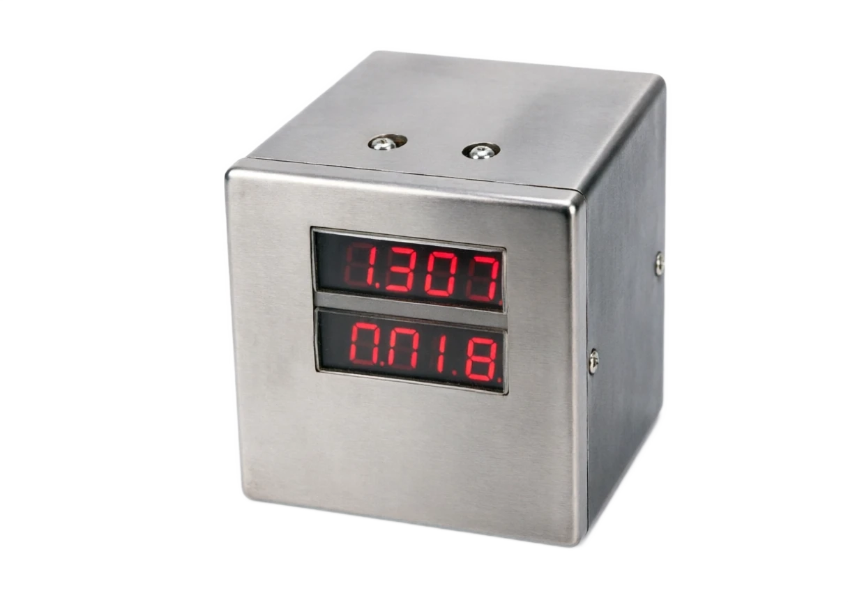
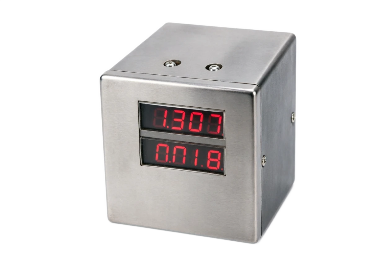
The whole machine is a standard disk (DIN size 96 x 96 mm is the main) instrument, with two visible windows and operating keys for the front plate, the core consisting of input plates, the master plate and the power drive, and the power plate is separated from the signal plate to contain contact spark interference.

Analysis of strengths and weaknesses

4.1 Advantages

4.2 Disadvantages and responses

Front panel.

Composition and function: Double row four LEDs (prescript PV/ sub-present SV or valve level); Automatic / Manual key, add or decrease key and group key; Status light (Auto/ Manual / Alert / Upper and Lower Level of Wall)

Enter a signal panel

Composition and function: Almighty Input Channel + Valve Feedback Channel (Perception Incentive Constant Source / Power Input); Signals insulated from Power, TVS protection

Console

Composition and function: MPU runs PID, server logic, self-recommended and diagnostic; parameter EEPROM is powered; real time clocks are used for event recording

Power Drive

Composition and function: Double relay (positive/ inverted, 5A / 250VAC) or solid state relay / controlled silicon; RC Extrusion Network; reverse interlocking circuits; isolation from signal plate light to remove sparks

Alarm output

Composition and function: 2-4 point relay alert (PV upper and lower, deviation, valve limit, feedback break, block)

Communication interface

Composition and function: RS-485 (Modbus-RTU), optional with ethnet; remote location control (surveillance PV/ SV / MV / WF and hand-to-hand status)

Power unit

Composition and function: 85 ~ 264 VAC extenuating; whole power ≤ 5 W (without driveback)

End subsector

Composition and function: Enter the endpoint (PV / SV / valve feedback), drive the endend (rotating / invert / public), alarm endpoint, power endpoint partitioning, driver endpoint with shield

Evolutional trends

Structure: Description Composition and function:

No Touchdown

Structure units: solid state relay / controlled silicon over zero trigger replacement mechanical relays, adapted to high frequency action profiles, without maintenance Composition and function:

Variables

Structure module: Interruptor structure: Simulation of volume speeds given + orientation contact, balancing accuracy with power soft startup composition and function:

Diagnosis deepening

Structure units: valve feedback breakers, electrical blockages, over-routing, number of actions statistics and life alerts, extension to health management of the implementing agency Composition and function:

Communications integration

Structure unit: Modbus / Ethernet access SCADA, remote hand switching and parameter management, becoming the small SCADA field control node Composition and function:

Two planes in one.

Note: Concort + server amplifier integration, saver equipment, saver cover, saver connection, single circuit cost and failure point significantly reduced

Valves are closed to high accuracy

Note: Location inner ring + dead zone + brake, valve control accuracy 1%; no external server amplifier flushing and backside problems

No Disturbing Switches and Tracks

Description: Hands / Automatic two-way no disturbance; valve tracking avoids transient instantaneous valve jumps and provides security for work

When self-assessing

Note: Relay feedback/ critical mass is self-reconciled, typical circuits are available within 30 minutes, free of manual touch-down

Agility in all-powerful input.

Note: mA / mV / V / Thermal teleprotocol/ Thermal electrical resistance is fully compatible, temperature, pressure, flow, liquid position loops

Protect function is complete.

Note: Feedback break-ups, blocking, over-routing, minimum action spacing, back-turning locks, protection of executing agencies and accused persons

It's a good economy.

Note: One-way investments are much lower than DCS return card + locator programmes, small and medium items and old device modifications preferred

Interrupt control nonlinear

Description and response measures: Bit-stagger output is the essential non-linear link, with small flow fine-regulating capacity weaker than continuous 4-20mA + locator; high precision requires a change to a continuous output option

Contact life limit

Description and response measures: Relay mechanical lifetime 100000 secondary, vulnerable to vibration or frequent disturbance of work-related contact points; Select solid state relay / controllable silicon type and set reasonable dead zones

Limited power of driver

The relay contacts can directly switch loads in the 5 A class. Use an external contactor for higher-power motors. Size the circuit for the actuator motor and add an interposing relay if necessary.

One-way pattern

Description and response: One turn, increasing the cost of round-trip occupancy; 8 Compare DCS / Small PLC Programs above return

Mark dependent on manual

Description and response measures: Valves are to be marked on site and re-marked after adjustments to the pole; incorporated into the regulatory overhaul of the implementing agency

No redundancy

Description and response: single circuit, instrument failure or circuit failure; vital circuits with side-tracking means of operation (operator / hand-held) or double-heat preparation

It can't be used on Ben Ann's way back.

Description and response measures: instrument not certified, direct power circuits associated with the driver ' s contact; electrical valve circuits in the hazard area shall be designed as a whole for the blast/enhanced system

04

APPLICATIONS

Application area

Smart server PID regulators are used mainly in single-way control situations, where the electric implementing agency is the end provider, and typically the industry is distributed as follows.

5.1 Five typical application models

Electricity

Typical application scenario: heater / boiler windgate control, speed circuit for coal machines, water level adjustment for oxygen deoxifiers Common configuration: valve feedback leveler type, full alarm

Metallurgy

Typical applications: furnace pressure (flue damper), gas flow control and soaking furnace temperature. A thyristor-driven configuration is commonly used for frequent actuation.

Construction materials and cement

Typical application scenario: negative pressure (wind door), raw material (triple valve), end-of-Kilon temperature

Chemical

Typical application scenario: temperature (vapour valves) for small and medium tanks, PH for waste liquid, wind wind doors, common configuration: all-powerful input, front-reward compensation

Water treatment

Typical application scenarios: additional measurements (regulating valves), exposure wind, back-scrambling intensity control

Heating air conditioner

Typical application scenario: Water temperature (electrical control valves) at heat exchange stations, New Windgate, Water tank fluid level Common configuration: economic, winter and summer mode switching

Mechanical equipment

Typical application scenario: test shelf temperature / pressure control, burner wind door, coated line temperature control Common configuration: compact 96 x 96 or 48 x 96

Mode

Typical application scenario: backtracking composition Common configuration: key points

Basic one-way circuit.

Typical application scenario: PV Sensor ⁇ Concortion (PID+servation) ⁇ Power valve ⁇ Valve feedback adjuster Usual configuration: most commonly used form; dead zone 0.5 ~ 1 %; precise process time parameter setting

Thread Control

Typical application scenario: main output external to the by-regulating, side drive electric valves Common configuration: typical temperature-flow chain; main continuous output, side-software

Front Feed + PID

Typical application scenario: front-drive feed channel + PID feedback, synthetic output drive electric valves Common configuration: detectable heat/ mix circuits for disturbance

Manual emergency circuit.

Typical application scenario: the regulator mode is directly inverting point operating valves Common configuration: hard manual point + soft manual increase or decrease; emergency response in DCS failure

I'm gonna have to get on the plane and monitor the circuit.

Typical application scenario: SCADA is remotely given by Modbus, the regulator is now closed

05

TECHNICAL SPECIFICATIONS

Technical Parameter Table

The following table shows the typical specifications for the smart server control PID regulator (96 x 96 disc mainstream machine type), which are based on the sample of the manufacturer.

  1. 01

    Select Table

The price is the price of a single renminbi.

7.1 Order code structure (example 8 bits)

  1. 01

    Selection Guide

8.1 Ten Elements of Selected Decision-Making

8.2 Typical scene selection path

8.3 Four procurement acceptances

Summary

Smart server control PID regulator = "Unique PID regulator + Internal server amplifier" integrated form to achieve an exact driver for a contact-driven electrically active agency in two closed rings (process PID outer ring + valve server inner ring). It complements the 42nd operator separation fence (emergency manual delivery), 45th intelligent separator (control output separation) and divides the work along the electric valve control chain, forming a complete toolbox under the control of the small and medium project electric valve. The log and control family in this series is starting with Part 48 (Paperless Recorder) and following up with alarm devices, patrol devices, etc.

Technical parameter table . Serial number / parameter itemCross-reference
Serial numberParameter ItemTypical specification
1Enter signal PVParity input: 4 - 20mA / 0 - 20mA; 0 - 20 mV ~ 0 - 20V; Thermotogram K/S/B/R/E/J/T/N; Thermotically Resist Pt100 / Cu50; Sampling cycle ≤ 0.5 s, Precision 0.2% FS
2Give signal SVThis machine is given with keys; remote with 4 - 20mA/ 0 - 10 V; communication given (Modbus); given with 0 ~ 9999 available
3Valve feedback inputThe power slot 500 ~10k (heat pressure incentive) or 4-20mA currents; full-open / full-stagger marked; feedback cutout detected and protective action (preserve / full-stagger) set
4Control OutputRelays positive / inverted double-touch 5A / 250VAC (dehibitability); or solid state relay (SSR) driver output; or controlled silicon over zero trigger (extraexposible / controlled silicon)
5Control algorithmPosition PID, Parameter P 0 ~ 999.9% / I 0 ~ 3600 s / D 0 ~ 3600 s; positive and negative; micro-column; fraction separation; saturation; self-refining (relay feedback method)
6Server ParametersDead zone 0.2~5% available; brake delay 0~10s; minimum action interval 0~60s; itinerary time 0~360s (to be judged in relation to blockage)
7Valve Control Precision±0.5% ~±1% (Lock Zone and Enforcement Gap Decision); Control Cycle 0.1 ~ 0.5 s
8Manual / automatic changeoverTwo-way no disturbance; automatic value tracking valve (MV = WF); soft manual (increase or decrease) and hard manual (reverse point movement)
9Alarm outputRelays 2~4 points: PV upper and lower limits, deviations, valve upper and lower limits, feedback breakers, blocking, action time out; contact capacity and driver contact points
10Communication interfaceRS-485 (Modbus-RTU) standard; optional to the `Modbus-TCP ' ; remote given reading and writing of all parameters; communication interruptions can set a reservation or a home-based appointment
11DisplayDouble row LED, Major PV (Project Volume), Subsistence SV / MV / WF toggle; Valve percentage and status light indicator
12ProtectReverse electrical interlocking; feedback breaker protection; blocking detection and alarm; ultra-route protection; minimum action spacing against electric overheating
13Power supply85 ~ 264 VAC 47 ~ 63 Hz or 24 VDC; power ≤ 5 W (without driveback)
14Environmental conditionsJob 0 ~ 50℃, Humidity ≤ 85% RH without Condensation; Vibration ≤ 0.1mm (10 ~ 55 Hz) Disk Load Environment
15Installation DimensionsPanel DIN 96 x 96mm Open 92 x 92mm (mainstream); compact 48 x 96mm; Panel protection IP54 (sealed circle)
16Insulation and securityEnter / Driver / Power Intersegregation 1500V AC; Driver Ender Shield; compliant with GB / IEC Console Security Standard
Technical parameter table · Slotting / Representing brand and seriesCross-reference
TrancheRepresentative brand and seriesTypical ConfigurationSingle-desk priceTypical applications
High-end domestic productionIon Yuen NHR-5300/ UW EAI seriesControlled silicon overzero trigger; self-regulating; Modb us + Ethernet; full diagnostic3000-6000 yuanIrresistence, up-to-date, integrated, vital back-way.
Domestic production standardsFukuoka / Far East / Main brandsRelay drive; self-refining; double display + alarm; RS-4851500-3000 yuanNew project main, generic, one-way
Universal national productionLocal instrumentator common seriesRelay drive; fixed input type; basic PID not self-regulated600 ~ 1,500 CNYGeneral circuits, renovations, budget sensitive.
Type of aircraft importedTrans-river / Fuss power utility PID+ externalImport a common PID+ stand-alone server amplifier group, few integrated servers5000 ~ 12,000 CNY• The owner designates import, special certification items
Technical parameter table . bits / MeaningCross-reference
bitsMeaningCommon take-up examples
1Broad categories of productsS = Smart server control PID regulator
2Panel Dimensions9(96×96);4(48×96);8(80×80)
3Input typeX (Universal input); K/S/E/P (Designated fraction number); A (electricity)
4Valve feedbackR (width) A (4-20mA); D (width / current compatible)
5Driver MethodJ (relays contact points); T (solid state relays driven); K (controllable silicon over zero trigger)
6Call the number.2 / 3 / 4 (relays alert points)
7Communication interface0 (nil); R (RS-485); E (Ethernet)
8OptionsV (Previous feed/ serial package); F (Variance frequency adaptor); default base
Technical parameter tables · Decision-making elements / Decision pointsCross-reference
Elements of decision-makingElements of judgement
Type of implementing agencyNo locator, touch-to-point electric agent is the main site of the instrument; locator/gas-to-refer to the continuous output regulator (part 45 separators in conjunction)
Driver SelectionLow frequency of action (within several times an hour) to select relay type; frequent action or long life requires the selection of a controlled silicon over a zero trigger type
Driver Power AccountingExternal contacts when the electrical current of the implementing agency exceeds the capacity of the contact point (5A) and account for the abundance of the contact point
Valve feedback formMaximum number of electrical feed; new project proposal 4-20mA electrical feedback is better against interference; confirmation of agency feedback compatibility with regulator input
Dead zone and precision.Control accuracy requires high-altitude but high-impact contact movements; general process 0.5-1% is sufficient; oscillation is appropriate to ease
Control function needsOne-way basics are sufficient; serial / pre-revenue needs selection package; complex multivariant and logical locks should be rotated DCS / PLC
Communications and integrationRS-485/ Ethernet; confirm retention strategy and recovery behaviour when communication is interrupted
Security and emergency responseImportant circuit side-by-side operations (Page 42 operator separation fence or manual operator); evaluation of the consequences of a single machine failure
Size of return route1~8 Return List Economy; 8 Return Comparison of DCS / Small PLC Combined Costs and Maintenance
Environment and protectionDisk environment 0~50°C; dust field sealing panel; vibrating site reinforced installation and evaluation of the wear and tear of the electrical feed
sceneRecommended programmeRationale
Boiler wind doors (high-frequency movements)Controlled Silicon Over Zero Trigger + 4-20mA Valve FeedbackLong life without contact; current feedback resistant to interference; blockage check
Water temperature (economic) at heat-replacement stationsNational Standard Substitutes + Levelr FeedbackWe're low on frequency, and relays are the best.
Negative Threshold Level of CKO (Main Cresary - Windgate)Thread-level package type, with a sub-module in the main.Serial level to improve disturbance response; side-stealing server drive windgate
Important circuits (no control allowed)Double-heat or operator sidewalk programmeMaintain manual control and secure security when the sheet fails
LinkThe point of acceptance.
1. Check-in on arrivalModel 8 bit-by-step check (size / input / feedback / drive / alarm / communication); driver contact capacity matching the agency ' s electrical parameters accounting book
2. Functional check / Valve at two points to verify the accuracy of the display of the valve; automatic hand-to-hand no-disturbing test; cross-locking and minimum action spacing item by itemCross-reference
2. Functional check-upsValves are marked with precision after two points are marked; hand-free transition test; cross-locking and minimum action spacing function is verified item by item
3. Control performance alignmentAccess to simulated objects or actual circuits for step-step tests; self-regulating and reviewing overtones and response times; blocking protection and feedback breakback protections; correct protection action
4. Communications and recordsModbus reading, writing and remote validation; communication interruption confirmation; alarm and incident record reconciliation; 72 hours continuous running test