PRODUCT TECHNOLOGY

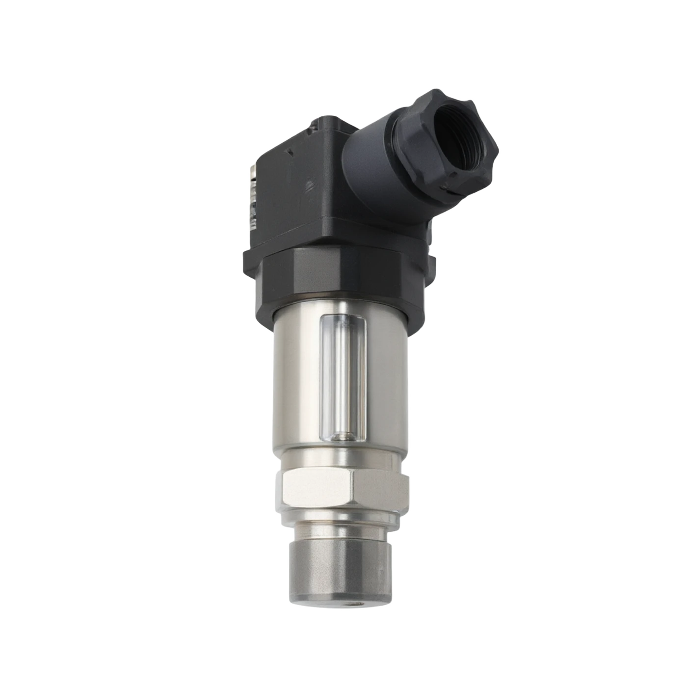
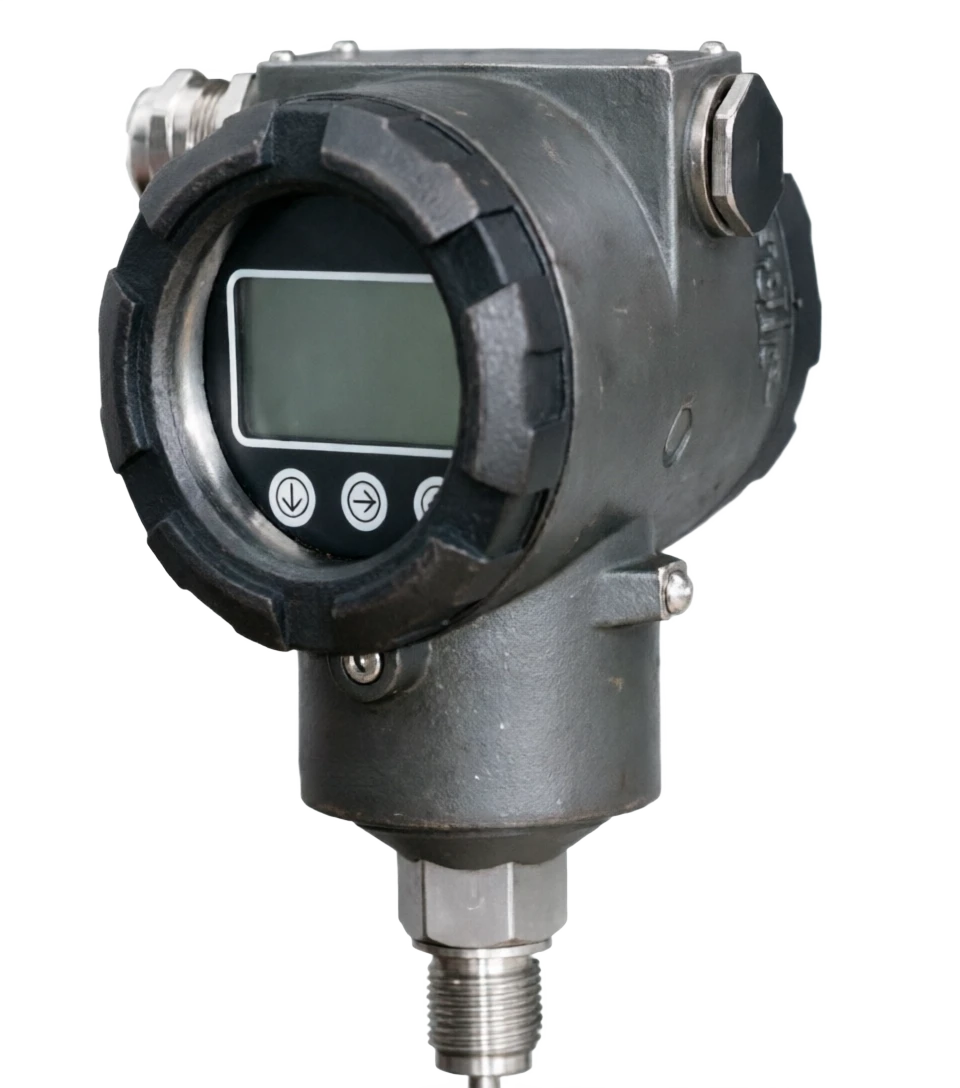
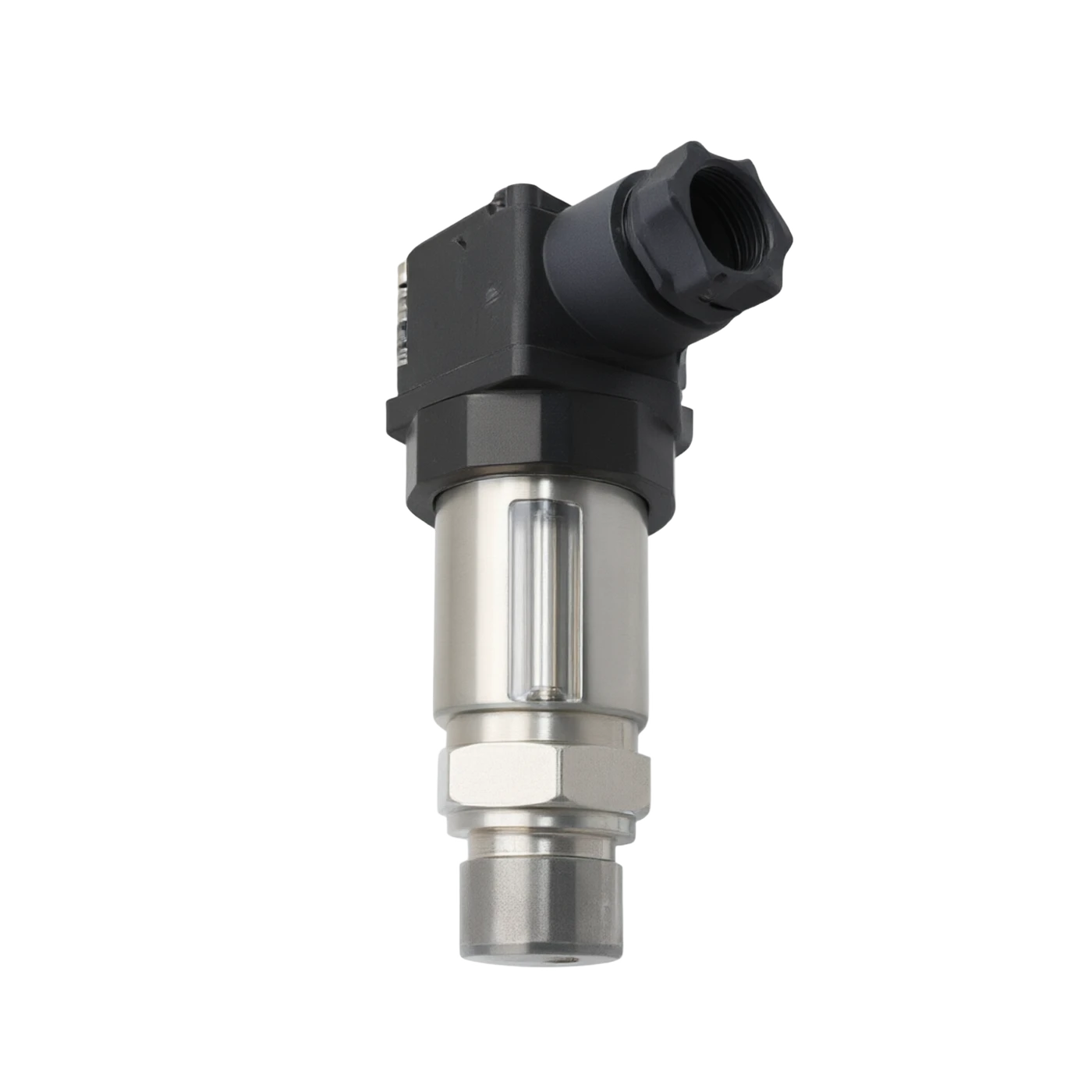
Smart diffusion silicon pressure transmitter

Operating principle

Smart diffusion of silicon pressure transmitters.

When the monolithic silicon material is subject to external force reaction, its crystal structure undergoes a slight transformation, leading to a change in the transport rate of the carrier, thus causing a change in the resistance rate of the silicon tablets, a physical phenomenon known as the pressure effect. The resistance is much higher than the sensitivity of the metal reaction film (usually 50 to 100 times the metal), so that the diffusion of silican sensitive elements can export larger telecommunications signals to facilitate subsequent magnification. The diffusion of silicon chips spreads 4 equivalent electrical resistances on silicon membranes, forming the Whistlen Bridge. (b) When no pressure is activated, the four arms of the bridge are equally resistant and the output is zero; When the pressure works on a silicon film, the two sets of resistance are subject to stress and pressure, respectively, and the resistance is in the opposite direction, the bridge is unbalanced and the output is proportional to the measured pressure.
Reference to the classification of intelligent diffusion silicon pressure transmitters
Smart diffusion of silicon pressure transmitter . Classification reference diagram

Smart diffusion silicon pressure transmitter selection support

Provide survey missions, media and installation conditions and obtain product configuration advice.

Contact us
Smart diffusion silicon pressure transmitter . Technical Note

TECHNOLOGY & APPLICATION

Understand the principles, the exact selection.

From measurement principles to field applications, the technical features and selection elements of the smart diffusion silicon pressure transmitters are understood.

01

TECHNICAL GUIDE

Overview

(Intelligent Diffused SiliconPressureTransmitter) is based on semiconductor pressure resistance, and the diffusion of the MEMS process on a single-crystalium silicon base to form a Heathon Bridge sensitivity component, which is supported by high performance magnification circuits, temperature and non-linear digital compensation techniques, and is converted into a standard form of industrial on-site instrumentation from measured pressure (watch pressure, pressure suppression, pressure differential, negative pressure, etc.) to a standard signal (4 ~ 20 mDC, HART, Modbus, PROFIBUS-PA, etc.).

Because of its high measurement accuracy, long-term stability, small size, wide range coverage, high overload resistance and its intelligent diagnostic and digital communication capabilities, it has become one of the most widely used electromeasurable pressure meters in industrial process control, energy measurement, fluid transport, equipment manufacturing, etc.

02

MEASUREMENT PRINCIPLE

Operating principle

2.1. Pressure effects

When the monolithic silicon material is subject to external force reaction, its crystal structure undergoes a slight transformation, leading to a change in the transport rate of the carrier, thus causing a change in the resistance rate of the silicon tablets, a physical phenomenon known as the pressure effect. The resistance is much higher than the sensitivity of the metal reaction film (usually 50 to 100 times the metal), so that the diffusion of silican sensitive elements can export larger telecommunications signals to facilitate subsequent magnification.

2.2 Whistlestone Bridge Structure

The diffusion of silicon chips is based on MEMS processes that spread 4 equivalent electrical resistance on silicon membranes, forming the Whistlestone bridge. When there is no pressure, the four arms of the bridge are equally resistant and the output is zero; when there is pressure on the membrane, the two resistances are subject to stress and pressure, respectively.

Measurement formulaClick to see the big picture
ΔU = U · ΔR / R
in

In contrast to resistance, the bridge is unbalanced, output is being delivered to a mV signal that is proportional to the measured pressure. ⁇ U: ⁇ U = U. ⁇ R / Rin. U is a constant current (or constant pressure) source incentive, ⁇ R/R is relative to the pressure.

in

2.3 Signal reconciliation and intelligent processing

The mV signal is amplified by a low noise instrument amplifier and sampled by a high resolution A/D converter and sent to MMU/DSP

Conduct

Zero and full range calibration (Zero drift compensation, Quantification);

Temperature compensation (zero point temperature drift, sensitivity temperature drift, multiple fraction compensation);

Non-linear compensation (multiple aggregation or checklist, increased linearity);

4 Quantities migration (user can set freely within the range) 4 ~ 20 mA Corresponding pressure values;

Digital communications (HaRT / Modbus / PROFIBUS etc.);

Self-diagnostic and fail-warning (sensor opening, short circuits, quantities, etc.).

The results are then converted to D/A to output 4-20mADC signal superheavy to HART digital signals, or directly to the control system by means of a live bus.

Page 2, WorkBuddy Collapse

03

PRODUCT STRUCTURE

The whole structure.

The whole machine is mainly sensitive elements, process interfaces, signal-processing circuit boards, shell and electrical connectors

The four main components are structured as follows:

[Pressure entrance] ⁇ [Secret film + silicate] ⁇ [Silin silian sensitive elements] ⁇ [Smallification and compensatory circuits] ⁇ [MCU/DSP digital processing] [output: 4~20 ma / HART / Modbus]

3.1 Main component parts

3.2 Typical structural forms

One Structure

Sensitive elements, circuits, displaying integration in the same shell, compact structure, and easy to install;

Divisional (apogee) structure

(b) The probe is separated from the surface by a catheter or cable and is applied in situations of high temperature, corrosive or invisible;

Pistol (health) structure

(b) The use of a polycreatic interface with a sanitary card, free of any horns, easy to wash, and meeting the requirements of GMP/FDA;

Blank pressure (bifur) structure

Double-separated film is connected to the differential sensitive elements through the cavity tube for liquid position, flow, differential pressure

Measurement.

Isolation diaphragm

Main function: Separating the detector medium from sensitive elements, transmitting pressure Common material: 316L stainless steel / Hapsy alloy C / tantalum

Fill with silicon oil

Main function: Transfer of pressure to sensitive elements, provision of insulation and insulation Common material: Silicon oil (dimethyl silicate)

Silicate sensitive elements

Main function: Convert pressure to telecommunications using the pressure resistance Common material: single crystal silicon + diffusion barrier Whistlen bridge

Base / Shell

Main function: Seal and mechanical support Common material: 316 L stainless steel

Signal processing panel

Main function: Magnification, Compensation, Linearization, Digital Communications Common Materials: Low Noise Transport + MMU + A/D

Connector / Cable

Main function: Power to signal connection Common material: gold plating endpoint / shielding cable

Show Table Header (LCD)

Main function: Show pressure/ current/ diagnostic in situ Common material: optional, 4-bit LCD

Process connection

Main function: Connect to pipe / packagings M20x1. Common materials: 5 / G1/2 / NPT1/2 / Frank / Guard

04

TECHNICAL GUIDE

Analysis of strengths and weaknesses

4.1 Main advantages

high measurement accuracy

Typical precision 0.1% FS, 0.2% FS, 0.5% FS, which meets industrial process control requirements;

Ranges Overwrite

From hundreds of Pa to 250 MPa, gauge/switch/ differential/negative pressure can be measured;

Long-term stability

Year drift ±0.1% FS, long useful life;

. Temperature compensation is complete

(b) Inline temperature sensors and multiple points compensation, with low temperature drift;

Page 3 · Compiled with WorkBuddy · ⑤ High overload resistance

(i) 1.5 to 4 times the range, in part more than 10 times;

-- speed of response.

(a) a msace response, suitable for dynamic pressure measurements;

Smart communication is powerful

Support for agreements such as HART, Modbus, PROFIBUS-PA, FF;

Stabilised, lightweight

(b) To facilitate on-site installation;

Media Compatibility Good

The amplification film is available for a variety of preservation materials.

4.2 Main shortcomings and responses

One, it's a lot of temperature.

The temperature factor for silicon materials is larger than that for metals and is compensated for by the built-in temperature;

. Limited capacity to withstand shocks and long-term overload

(b) Strong impact or long-term large overloading that may damage silicon film;

. Sensitivity to installation

(b) Installation of excessive twists or tube vibrations may introduce errors and require proper installation;

Prices higher than capacitor/corture delivery

(b) Weaknesses in low-cost environments;

Long-term silicate age or sealing lapses

(b) May cause drift or leakage, which requires periodic inspection;

EMPRETECTIONAL ENVIRONMENTAL SENSIVE

The blast-proof type is selected for high-level electromagnetic interference, in which the ground is well connected and shielded.

Page 4, WorkBuddy

05

APPLICATIONS

Application area

Because of its characteristics of performance stability, wide range of quantities, signalling generality, intelligence diagnosis, etc., in the following industrial areas:

Wide application

Petroleum chemicals

Typical uses: reaction blankets, pipelines, tank pressure monitoring; oil and gas pipeline pressure and differential measurement

Electricity and heat

Typical uses: boiler steam, water delivery, condensed water pressure; motor lubricating oil pressure monitoring

Metal and metal

Typical uses: pressure on furnaces, trans-manufacturing, casters hydraulic system; pressure on cooling water cycle

Water treatment and water

Typical uses: water pipeline network, sewage, water purification plant pumping station pressure; dam seepage and fluid level

Food and pharmaceuticals

Typical uses: CIP/SIP Cleaning Pressure, Fermentation Cans Pressure, Pure/IDU System (sanitation type)

Paper and textile

Typical uses: slurry, steam, baking tank pressure, tension control system

Hydraulics and gas.

Typical uses: hydraulic stations, gas sources, pre- and post-service valve pressure, mechanical equipment state monitoring

Aerospace and automobiles

Typical use: engine fuel, hydraulic pressure, brakes, barometers

Building and heating

Typical uses: HAC system pressure, building self-control, intelligent water

New energy

Typical uses: lithium cell electrolytic pressure, hydrogen gas tank pressure, wind hydraulic system, photovoltaic polycrystalsilic process

06

TECHNICAL SPECIFICATIONS

Main technical parameters

The following table shows the main technical parameters of typical intelligent silica diffusion pressure transmitters, the actual values of which are based on the specific model specifications of each plant.

Page 5, WorkBuddy, page 6, WorkBudy,

Main technical parameters · Parameter item / Typical specification / RangeCross-reference
Parameter ItemTypical specification / range
Measurement typeWatch pressure (G), pressure stress (A), pressure differential (DP), negative pressure (vacuity)
Measurement range0~200 Pa... 0~250 MPa (multi-segregation)
Accuracy class0.1% FS / 0.2% FS / 0.5% FS (linear, delayed, repetitive)
Long-term stability≤ ±0.1% FS / Year; thallium ±0.25% FS / 5 Year
Zero o'clock.≤ ±0.05% FS / 10℃ (typical); ⁇ ±0.1% FS / 10℃ (maximum)
The sensitivity is warm.≤ ±0.05% FS / 10℃ (typical)
Output signal 4-20MA DC (biline); 4~20 MA + HART; Modbus RRU (RS-485); PROFIBUS-PA
Power supply12~36 V DC (HART typical 24 V DC); security fence for this type
Load capacityRL ⁇ (Us 12 V) / 0.02 A (4 ~ 20 mA output)
Media temperature 40 °C~ +85 ℃ (standard); 40 ℃ ~ +200 ℃ (high temperature); ~ 40 ℃ ~ +400 ℃ (distant)
Ambient temperature40 °C ~ + 85 °C; storage 40 °C ~ + 100 °C
Range migration ratioTD = 100:1 (modifiable)
Main technical parameter 1.5~4 times the excess / mass range (slot by scale); partial pressure can be 10 timesCross-reference
Overpressure / Overload1.5 to 4 times the scale scale (segregated by the scale); partial pressure of 10 times
Resist impact / vibrateImpact 50 g / 11 ms; vibration 20 g / 20 ~ 2000 Hz (typical)
Electrical connectionM20x1.5 / G1/2 / NPT1/2 cable seals; optional aviation plugs, waterproofing interfaces
Process Connection M20x1.5, G1/2, NPT1/2, NPT1/4, PN50, 1/2 " NPT plane, Kag (sanitary type)
Housing material316L stainless steel (standard); aluminium alloy (low cost); Haq alloy / tantalum (strong corrosive)
Isolation diaphragm316L / Hapsy Alloy C-276/ tantalum/ Monnar/ titanium / gold (strong corrosive)
Ingress protectionIP65 / IP67 / IP68 (Dive)
Explosion protection markingEx iIC T4~T6 Ga; Ex d IIC T4~T6 Gb (Benan/ Insulation)
Response time≤ 30 ms (default); fastest ≤ 5 ms (modifiable)
Display type4 bits LCD (backlight) showing pressure / current / percentage / diagnostic information
Distance from communicationHART ≤ 1500 m (shield double winch); Modbus ≤ 1200 m
WeightAbout 0.5 ~ 2.5 kg (different by structure and interface)
07

SELECTION GUIDE

Selected guidelines and selection tables

The correct selection is key to ensuring the long-term stability of the carrier. It is recommended that the following steps be followed: clearly measured object: measured medium, phase, corrosiveness, particle content / crystallity;

Determination of type of measurement

(a) Watch/ press/ pressure/ differential/negative pressure;

Determination of the scale

Normal pressure / maximum working pressure / minimum working pressure, with a recommended scale of 1.5 ~ 2 times the normal pressure;

Determine precision

Select 0.1% / 0.2% / 0.5% FS according to the process requirements;

-Pertify output signal

Simulation of 4~20 ma / HART / Modbus / PROFIBUS-PA;

Process interface identified

Splines, Frank, Carpenter, sanitary interfaces;

Determination of the temperature of the medium

Standard / high temperature / long-distance;

- Determination of blast and protection levels

Benan/Insulation, IP65/67/68;

Determination of material

(a) Crust / Isolated film / O Circles and Media Compatibility;

Identification of additional functions

Show the surface, smart diagnosis, mine protection, wave control, etc.

7.1 Selective schematic tables

Page 7, WorkBuddy

7.2 Examples of typical job profiles

Page 8, WorkBuddy Collapse

Selection guide and selection table . Serial number / Selection elementsCross-reference
Serial numberSelective ElementsOptionsApply scene / description
1Measurement type& GulpFor relative atmospheric pressure measurements, most commonly used
Insulation (A)Vacuum, sealed containers, gas-screech measurements
Difference pressure (DP)Flow, fluid level, filter pressure differential
Negative / VacuumVacuum pumps, distillation, suction systems
2Measuring span0~10 kPa…1 MPaMicropressure: wind pressure, clean room, flue gas
0~1 MPa…10 MPaModerate pressure: water, hydraulic pressure, gas source
0~10 MPa…250 MPaHigh pressure: hydraulic pressure, water injection, oil and gas wells
3Precision0.1%FSTrade measurement, precision control
0.2%FSProcess control, energy consumption measurement (recommended)
0.5%FSGeneral monitoring, HVAC
4Output signal4~20 mAGeneric Simulation Signal
4~20 mA + HARTCompatible simulation, grouping and remote debugging
Modbus RTU (RS-485)Multinodes, PLC/ Handler
PROFIBUS-PA / FFDCS bus system
5Process connectionM20×1.5 / G1/2 / NPT1/2General industrial pipeline
Selective guide and selection table . NN50 PN16 Frank/ Large pipe, storage tank, liquid levelCross-reference
PN50 PN16 FrankLarge pipes, tanks, liquid slots
1-1/2" / 2" Tri-ClampFood / Pharmaceutical Health Level
6Process medium temperature40~+85 ℃Temperature medium
40~+200 ℃Steam, heat, hot water
40~+400 °C (apogee)High temperature furnaces, steam pipes.
7Materials316L + Silicon oilGeneral water, oil, gas
Haq Alloy C-276Acid, alkaline, wet HCl
tantalum / goldCorrosive, water, wet chlorine.
8Detonation/protectionEx ia IIC T6BEN (Zone 0/1)
Ex d IIC T4Interruption (Zone 1/2)
IP67 / IP68Outdoor / wet / short-term dive
9Additional functionsLCD DisplayShow pressure/ current in situ
HART Handiman GroupRemote Zero / Modifier
Mine-proof, radio-frequency interference.Minister of State, cable, thunderstorm zone
Self-diagnostic/ status monitoringPredictive maintenance
Selective guidance and selection table . Work / Recommended typeCross-reference
WorkType of recommendationRecommended Specifications
Steam boiler bag pressure.Pressure + height 0 ~4 MPa0.2% FS, 4~20 ma+HART, 316L, Media Temperature +250
Urban water network pressurePressure +IP680 ~1.6MPa,0.5%FS,4~20 mA,316L,M20×1.5,IP68
Reaction Liquor (discretion)Fragment + Frank 0~10 kPa DP, 0.2% FS, HART, double DN50 Frank, 316
CIP Cleaning Backway PressurePressure + Health type 0~500kPa,0.2%FS,HART,2" Tri-Clamp,Ra ≤ 0.
Hydrogen tank pressureWatch pressure + Benn + Mine-protected 0-10MPa, 0.2% FS, HART, Ex i IIC T4, 316 L+ gold plating
Hydraulic station system pressureWatch + Overload0~35 MPa, 0.5% FS, 4~20 MA, 316 L, overload 4 times
08

TECHNICAL GUIDE

Installation and maintenance elements

8.1 Installation Attention

  1. 01

    (b) Installation should be far from vibration sources, and electromagnetic interference, with additional and deviation support frames, if necessary;

  2. 02

    The extraction vent position should reflect the process pressure and avoid being located in a vortex, dead zone or aqueous fluid;

  3. 03

    Pressure-thrust tubes shall be kept at an appropriate gradient, a slope-to-pressure point at the time of gas measurement, and a slope-to-transmitter at the time of liquid measurement;

  4. 04

    Prior to installation, the placard parameters should be checked for consistency with the medium, the Quantification, the signal, the interface, the blast-proof level;

  5. 05

    The wire should be made available using shield cables, with the shield layer being grounded at one end, avoiding parallel placement with power cables;

  6. 06

    High temperature media should be accompanied by condensers or apogee devices to protect sensitive elements.

8.2 Points for daily maintenance

  1. 01

    (b) Periodically inspect the appearance, seal, display and connection;

  2. 02

    Regular zero and quantum validation with a HART hand-manufactor or a top-up machine;

  3. 03

    Periodic cleansing of isolated film during the mass containing particles or crystals;

  4. 04

    (b) Long-term stoppages should close root valves, remove debris pressure and, if necessary, be stored in dry environments;

  5. 05

    When there is a visible drift or no output, the power supply, connection, load should be cleared and the repairs considered.

09

TECHNICAL GUIDE

Summary

One of the most widely applied electronic pressure meters in the field of industrial automation, with high sensitivity in the MEMS process, sound intellectual compensation, a rich output signal and an optional HART/Modbus/PROFIBUS-PA communication interface, covering almost all industrial scenarios from micropressure to hyperpressure.

In the actual project, the combination of measurements of objects, media properties, quantities, precision, output, process interfaces, temperature, blast and protection levels, additional features, and the standard installation and regular maintenance of the device should be combined to achieve the full integration of the diffusion of silicon pressure transmitters in terms of accuracy, stability and intelligence.

– End of document – Page 9: WorkBuddy