PRODUCT TECHNOLOGY

Convey radar positionometer

Operating principle

The trajectories of the radar.

The working method is the same as radar ranging: a nanosecond low-power electromagnetic pulse is fired at the detected medium, a reflection occurs at the surface of the medium constant ⁇ r different medium, a distance is obtained by measuring the time of transmission of the electromagnetic wave t D, and the height of the H inverse position is installed L:D = c t / 2 (c≈ 3×10⁸ m/s for light speed) ⁇ L = L -L (interface measurement: upper liquid level - lower liquid level = thickness of interface layer) The backwave strength of the transport radar is determined by the medium constant difference between the two media. Even lower detector ⁇ r (e.g. ⁇ r= /GuidedWaveRadar 3 page technical summary technical document. Select manual guide radar positionometer) because of the electromagnetic wave energy being bound to the conductor

  1. 01

    1 . Pulse generator . Generates a nanosecond low voltage pulse (Vmax ≈ 1 ~ 5 V)

  2. 02

    2 Electronic module switching Passing high-speed switches into the conductor.

  3. 03

    3 . Conveyment of the ..or direct transmission along the ..

  4. 04

    4 . Media Surface Reflection . Facing the ⁇ r Differing Interface, Reflecting the Conveyor

Convey radar position tabulation support

Provide survey missions, media and installation conditions and obtain product configuration advice.

Contact us
· Technical note

TECHNOLOGY & APPLICATION

Understand the principles, the exact selection.

From measurement principles to field applications, the technical characteristics and selection elements of the conductor radar positional index are understood.

01

TECHNICAL GUIDE

Overview

(Guided Wave Radar Lever Meter, GWR) Contact-type object instrument based on the TDR time-area reflection principle. The electromagnetic wave is transmitted downwards along the conductor (column pole, coaxe, soft cable) and is re-entering the path after a reflection of the surface of the medium, with the electronic unit detecting the delay in the time of the pulse and the echo, and seeking the altitude of the object.

(a) Because of the Electromagnetic Wave being bound to spread in the conductive, the conductive radar has three distinct advantages relative to the normal non-contact radar: one low-media constant ( ⁇ r ≥ 1.4) can also be stabilized; Anti-sliding, anti-foam, anti-vapour; An interface can be measured simultaneously (e.g., an oil-water interface). The preferred positional instrument is in small containers in the oil, chemical, hydro and other industries, and in the scenes of the heavy work.

02

MEASUREMENT PRINCIPLE

Modus operandi (TDR time-frame reflection)

2.1 TDR Time-Strend Base

The work is the same as radar range.

A nanosecond low-power electromagnetic pulse is fired at the detected medium, reflecting on the surface of the medium constant ⁇ r, measuring the time of transmission of the electromagnetic wave, t.

Inverse altitude L:D = c t/ 2 (c ⁇ 3×10⁸ m/s for light speed)

Measurement formulaClick to see the big picture
D = c t / 2 (c ⁇ 3 x 10⁸ m/s for light speed) L = H - D (H install reference height for instrumentation, pre-marked) ⁇ L = L - L (interface measurement: upper-level liquid position - lower-level liquid position = thickness of interface)

2.2 Signal transmission path (8 steps)

2.3 Reaction intensity and communicator constants

Measurement formulaClick to see the big picture
⁇ r lower (e. g. ⁇ r = 1.5~3

The echo strength of the radar is determined by the medium constant difference between the two media.

  1. 01

    5~3

The light oil, liquefied gas (LPG) can also be measured in a stable manner, which is the greatest advantage of conductivity radar over non-contact radar.

/GuidedWaveRadar, p. 3 Technical Summary Technical Document . Manual of Selections Guided Radar Placer/GuidedWaveRadar, p. 4 Technical Summary Technical Document . Manual of Selections

Modular (TDR time-frame reflection) . Serial number / linkCross-reference
Serial numberLinkCritical handling
1Pulse generatorGenerates a nanosecond low voltage pulse (Vmax ⁇ 1-5 V)
2Electronic module switchingQuick-speed switches into the conductor.
3Conveyor transmissionDirected along the conductor. Energy concentrated.
4Media Surface Reflectionencounters ⁇ r difference interface, reflect back to the conductor
5RebroadcastHigh-speed sampling keeps the circuits collecting backwaves.
6Time-area analysisTest time difference t, converted to D
7Algorithm recognitionIdentification of main liquid position, interface, false echoes
8D/A Output4~20 ma+HART/ FF/ PA output
Modular (TDR time-frame reflection) • Media-Media constant ⁇ r / Reflection intensityCross-reference
Media-Media Constant ⁇ rReaction intensityTypical mediumMeasuring difficulty
1.4 ~ 3Weak reflection (conductive radar detectable)Liquefied gas, light oil, liquid hydrocarbonsMedium (non-contact radar difficult to detect)
3 ~ 10MediumOrganic solvents, alcohol, edible oilLow
10 ~ 80StrongWater, acid, alkalin, salt solutionLow, easy to measure
03

PRODUCT STRUCTURE

Product structure

3.1 List of main components (10 major components)

/GuidedWaveRadar, p. 5, technical summary document — optional manual

Shell / End cap

Main functions: IP67 Protection, to accommodate electronic modules 316 L

Show Modules

Main function: LCD / OLEED displays measurements, wave shapes, commonly used materials: glass + PC

TDR Pulse Module

Main function: Pulse occurrence + high-speed sampling + Time domain recognition

Signal processing MMU/DSP

Main function: Rebroadcasting, temperature compensation, communication Usage material: ARM / DSP

Communication interface

Main function: 4~20 ma + HART/ FF/ PA / Modbus Usual Materials: Connector Terminal

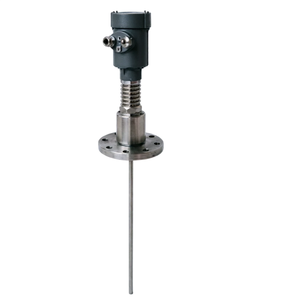
Conveyor (probet)

Main function: Transfer of electromagnetic waves, rigid poles/synthesis/cables, commonly used materials: 316L / PTFE / Hapsy alloy

Process Connecting Frank/Sniff

Main function: Linking to tank machinery Common material: 316 L / Haps alloy

Seal

Main function: Prevent media from entering electron cavity Common material: FKM / EPDM / FFKM

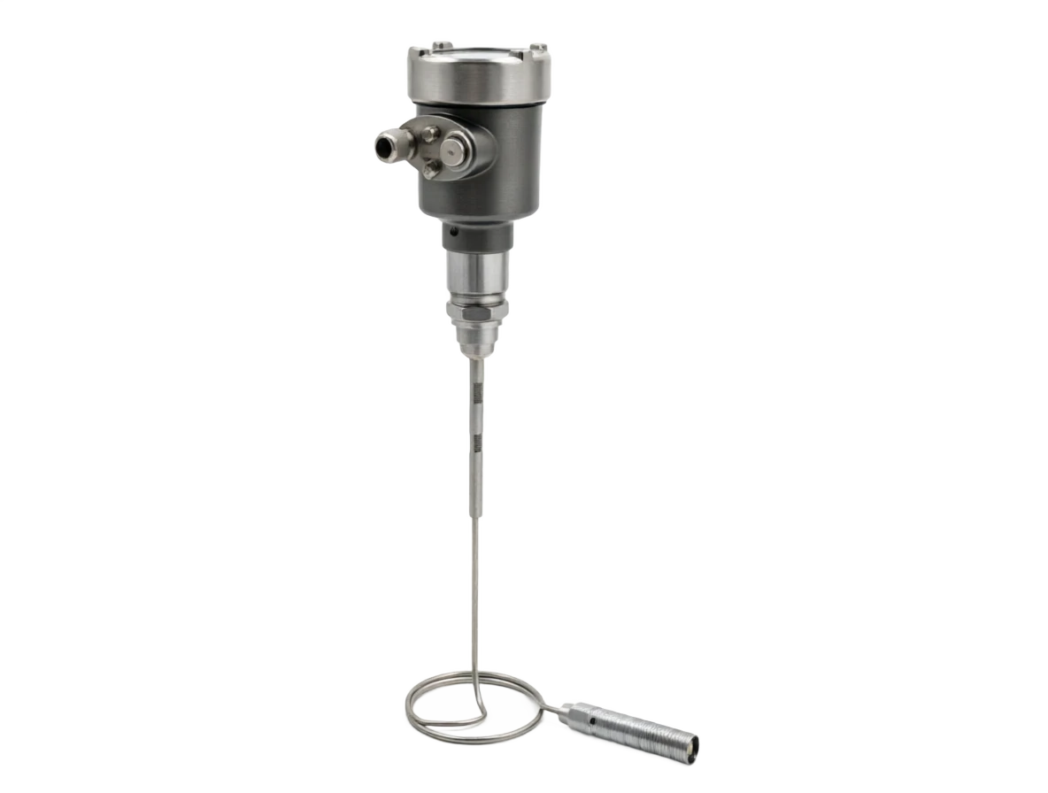
Weight / anchor

Main function: Cable probe bottom pulls straight and stabilizes. Common mass: 316L hammer.

Mine/ Wave Control Module

Main function: Mine-proofing, voltage protection

Transporter Type

Component name: Structure Main function: Quantities Usage Usage: Application of scene characteristics

- A hard one.

Component name: Single metal pole/package pole Primary function: ≤6 m Usual material: small reaction pads, process tank simple structure, anti-side disturbance weak

Coaxial tube

Component name: Main function: ≤6 m Usual material: low ⁇ r liquid, strong current, energy concentration, maximum resistance to interference

Soft cable (steal cable)

Component name: Steel wire + weight Main function: ≤30 m Usual materials: large stand-up tanks, wells, oil tanks Maximum Quantities, Curvable

Soft cable (package)

Component name: Steel cable + PTFE/PVDF Mask Primary function: ≤25 m Usual material: strong corrosive medium Corrosive resistance, adhesive resistance

Double pole.

Name of component: two parallel metal poles. Main function: ≤6 m Usual material: low- and medium-gluid liquids structurally stable, medium price

Mounting

Component name: Application of scenes Main function: Quantification Process Usual material: Remarks

The top of the flannel.

Component name: Standing cans, top of Reaction Pu, Main function: pole ≤6 m / Cable ≤30 m Usual material: most commonly used

Top Snail

Name of component: Small packagings, process tanks ≤3 m Usual material: G1 ½ / G2 Thread

Side-to-side (by-side pipe)

Component name: Strong current, high sticky, glucose medium Main function: ≤4 m Usual material: side pipe + reflector

In the tube.

Component name: Very low ⁇ r / strong condition Main function: ≤6 m Common material: electromagnetic wave dissemination inside the tube

04

TECHNICAL GUIDE

Analysis of strengths and weaknesses

4.1 Main advantages

/GuidedWaveRadar, p. 6, Technical summary technical document — Handbook of Options

4.1 Main advantages

Low-detectable ⁇ r medium

Note: ⁇ r ≥ 1.4 Liquefied gas and light oil are detectable (non-contact radar is difficult to detect).

Resisting flow / counteracting foam

Note: EMPs spread along the conductor body, free from internal disturbance in the tank

Anti-vapour / Dust

Note: The internal vapour, condensation, and non-interference measurements

Measurable Interface

Note: both oil and water interfaces, total liquid level (two-vertical recognition)

High accuracy of measurements

Note: ± 1 mm, repeatability ± 0.5 mm

Come on, come on.

Note: 1 ~ 3 seconds

Not sensitive to tank shapes.

Note: No rule shape required, barrier avoided

Support for multiple communication protocols

Description: HART / FF / PA / Modbus

Disadvantages and use restrictions

Contact measurements, conductor-like adhesives

Response: Select PTFE coating / coaxial tube / blow-clean interface

Not applicable to corrosive conductor medium

Response: Select PTFE / PVDF Full Plastic Cable

Cable probes need weight, cans are big.

Response: ≥300 mm space reserved at the bottom of the tank

Not applicable to large solid particles

Response: particulates damage the conductor

The hard rod is weak in sideways.

Response: Additional direction ring / Selecting axle tube type

Strongly broken in the can, it could damage the cable.

Response: Avoid the mixing area ± 1 m range

05

APPLICATIONS

Application area

/GuidedWaveRadar, p. 7, Technical summary technical document — Handbook of Options

Oil / Gas

Typical applications: crude oil, finished oil, light oil, liquefied gas tanks Recommended detection form: coaxial tube / cable

petrochemicals/ chemicals

Typical applications: Reaction plumes, acid-alkali tanks, strong corrosive tanks Recommended detector form: PTFE packaged plastic cables / coaxis

Electricity / Energy

Typical applications: Condensation, water, lubricants tanks

Water / Water

Typical applications: water tanks, sewage wells, deep wells

Pharmaceuticals/ Food

Typical application: CIP, feedstock, fermentation cans

Paper / Chemical

Typical applications: black, green, strong current cans

LNG / Low Temperature

Typical applications: LNG tanks, LNA tanks

Oil–water interface

Typical applications: oil water separators, oily sewage tanks Recommended probe form: same axle tube + double-liquidation algorithm

Focus / Coal Chemical

Typical applications: tar tanks, kerosene tar, strong currents Recommended probe form: Cono-axis / PTFE package

Small Response

Typical application: laboratory, mid-test device Recommended probe form: rigid pole ≤3 m

06

TECHNICAL SPECIFICATIONS

Technical Parameter Table

/GuidedWaveRadar, p. 8 Technical summary technical document — Handbook of Options

Technical Parameter Table · Parameter Category / Parameter NameCross-reference
Parameter CategoryParameter NameTypical specification
Measuring PerformanceMeasurement principleTDR time-scale reflection (Equivalent Time Sampling)
Measuring PerformanceMeasurement range0.3~6 m (bar)/0.5~30 m (cable)
Measuring PerformanceMeasurement accuracy± 1 mm (standard)/ ± 5 mm (cable long range)
Measuring PerformanceResolution0.1 mm
Measuring PerformanceRepeatability±0.5 mm
Measuring PerformanceResponse time1~3 s (modifiable, fastest 0.5 s)
Measuring PerformanceInterface MeasurementSupport for double echo (Line + Interface)
Process conditionsProcess medium temperature40 ~ +200 ℃ (standard)/ +450 ℃ (with cooling)
Process conditionsProcess pressure1 ~ +4 MPa (standard)/ 40 MPa (high pressure)
Process conditionsMedia-Media Constant ⁇ r≥ 1.4 (weak reflection better than non-contact radar)
Electrical specificationsElectricity voltage16~36 V DC(two lines)/24 V DC ± 10% (four lines)
Electrical specificationsOutput signal4~20 mA + HART 7 / FF H1 / Profibus PA / Modbus
Electrical specificationsLoad resistance≤ 600 (HaRT)/ 250 (Ben)
Electrical specificationsWork≤ 1 W (two lines)
StructureProbe material316L / PTFE / Hapsy Alloy C-276/ titanium
StructureProcess connectionG1 ½ / G2 Snail, DN50 ~ DN150 Frank.
StructureShell protectionIP66/IP67/IP68
Fireproof.Explosion protection markingEx d IIC T6 Ga / Ex ia IIC T6 Ga
Fireproof.Bomb protection certificationNEPSI / ATEX / IECEx / FM
AuthenticationCommunication protocolsHART 7 / FF / Profibus PA / Wireless HART
EnvironmentAmbient temperature40 ~ +80 ℃
EnvironmentRelative Humidity0~100% RH (cooled condensation)
07

SELECTION GUIDE

Select Table

7.1 Type by Punctuation

7.4 Type by Temperature Pressure

/GuidedWaveRadar, p. 9 Technical Summary Technical Document . Manual of Selection Guided Radar Placers/GuidedWaveRadar, p. 10 Technical Summary Technical Document . Manual of Selection

Select Table . Code / Spectator TypeCross-reference
CodeProbe typeRangeApply scenePrice slot
PR-R- A hard one.≤6 mSmall response chute, process jarLow
PR-DDouble Parallel Bar≤6 mMedium-Linkity, DisturbationMedium
PR-CCoaxial tube≤6 mLow Zir, Strong Stream, InterfaceMedium High
PR-LSteel cable.≤30 mLarge cans, wells, cans, large space.Medium
PR-LPPlastic cable (PTFE/PVDF)≤25 mCorrosive, acidic.Medium High
PR-SHealth level (316L mirror polishing)≤4 mFood / Pharmaceutical / CIPHigh
Range of ⁇ rReflection LevelRecommended probe.Application cases
εr ≥ 10Strong ReactionAny form is stable.Water, acid, alkaline solution
3 ≤ εr < 10MediumStick / ConoaxialOrganic solvents, alcohol, edible oil
1.4 ≤ εr < 3Weak reflector (conductive radar strong)Must be axle tube / packaged plastic cableLiquefied gas, light oil, liquid hydrocarbons
CodeApplicationsRecommended probe.Recommended frequency segment/materialRemarks
SC-01Liquefied gas storage tanksCoaxial tube316L / PTFELow ⁇ r Strength
SC-02Crude oil / Heavy oilDouble pole / Coaxophone316LPrevention of the impact of the attached material
SC-03Oil–water interfaceCoaxial tube316LDoubleback recognition
SC-04The acid is corrosive.PTFEPTFE / PVDFFull plastic corrosive.
SC-05Strong stream reactionCoaxial tube316LOptimistic against currents.
SC-06Small Response- A hard one.316L≤3 m recommended pole
SC-07LNG / Low TemperatureCold Bar316L low temperature196 °C cryogenic
SC-08Sewage / Clearing PoolCable (weighted)316L≥6 m shall select a cable
SC-09Food / Pharmaceutical CIPHealth poles316L Mirror polishedMatch 3-A / EHEDG
SC-10tar / strong corrosive mediumPTFE Packaged Plastic CablePTFE / PVDFIt's a good job to protect the gear.
Table of selected types · Temperature range / Recommended specificationCross-reference
Temperature RangeRecommended SpecificationsPressure ratingRemarks
≤ +120 ℃GenericPN16~PN40Standard process tanks
+120 ~ +250 ℃Heat typePN16~PN40Sealed with high temperature + heat spread
+250 ~ +450 ℃Super-heat + coolPN16~PN40It's cooling or blowing.
40 ~ -196 ℃LNG cryogenicPN16~PN40With cryogenic seals
≤ +4 MPaStandardPN40General industry
4~10 MPaHigh pressure typePN63Oil field watering
> 10 MPaSuper-high pressure.PN100~PN160Customisation required
08

SELECTION GUIDE

Selective guidance and trouble-checking

8.1 9 Step Process

/GuidedWaveRadar, p.11, Technical Summary Technical Document . Select Manual Guided Radar Placer/GuidedWaveRadar, p.12, Technical Summary

Selective guidance and troubleshooting . Step / ContentCross-reference
StepsContentsCritical judgement
1Clearly measure objectsSingle / Double / Strong Flow
2Verify the relative permittivity εᵣ of the medium.⁇ r ≥ 1.4 (conductive radar detectable)
3Determine the scaleBar ≤6 m, cable ≤30 m
4Determine process temperature pressureHigh temperature +450 °C/ High pressure 40 MPa
5Determine the probe formpole / homogeneity / cable / packaging
6Determine process connectionThread / Frank / Cassette
7Determination of blast/protectionEx d / Ex ia + IP67/IP68
8Establishment of communication protocolsHART / FF / PA / Modbus
9Assess the inside of the tankKeep space on the bottom of the can and avoid mixing.
Serial numberAttentionReason
1Cable probes need to be stored at the bottom of a ≥300 mmKeep the probe from bending to the bottom.
2Avoid the mixing area ±1 mTo prevent the cable from being entangled by a mixer.
3Avoiding the feed at the bottom.Preventing input impact on the damage spot.
4The metal cans are unreachable.- To prevent short-circuit damage.
5Keep the carrier vertical (discussion < 1°)Guaranteed accuracy of measurements
6PTFE-packed plastic cable for powerful corrosive mediaPreventing the erosion of metal detectors
7Open-air shieldingUV-resistant, rain-resistant snow
8Sniffed with a sealed raw beltGuarantee IP68 protection
9Mine-affected areas and wave-scrambling protectionProtection of communications interfaces
10Observe echo curves when debuggingDismantling interference, confirming main echoes.
Fault phenomenaPossible causeMeasures to address
Measured jumpStrong current / foam / interference echoSelect Axes / Set Bottom Block
Low measuredMedia mount / Cable bend / InterferenceClean the probe / remark
High measuredUnderlying interference error identification.Set a floor shield area
Selective guidance and trouble-shooting • Fault phenomena / Possible causesCross-reference
Fault phenomenaPossible causeMeasures to address
Show E14The echo is lost.Check the probes, the media, the ⁇ r.
Interface is not clear.The oil interface is not clear.Adjust thresholds / coaxial tube resistance
No display/ Power failureCheck 24V, load resistance.
Electricity constant 4 MAThe instrument's down.Check HART fail code
Electricity constant 20 maThe instrument's fail-safe.Check the range settings, back signal.