
StickClick on the picture to zoom in.
PRODUCT SPECIFICATIONS
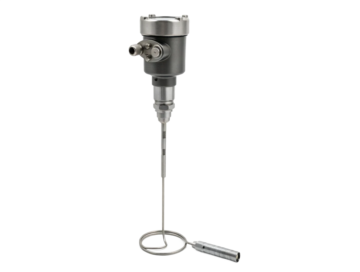
LISEN-RA-250
- The calibration of the radar.
A conductor radar (LIT) position counter, pole configuration.
01
Classification: Guided radar positionometer
02
Structure form: pole
TECHNICAL SPECIFICATIONS
Technical specifications
Check the specifications against your operating conditions and use the selection tables to confirm your order configuration.
View selection tables ↓| Model | LISEN-RA-250 |
|---|---|
| Measurement principle | TDR time-area reflection: microwave Pulse spreads along the wave pole, reflects on the surface of the medium, calculates the position by time difference |
| Measurement type | Level (L) / Liquid - liquid interface (I, dielectric constant differential ≥10) |
| Measurement range | 0.3–6m (bar long optional 0.5/1/2/3/4/6m) |
| Measurement accuracy | ±3mm or ±0.05%FS (takes big) |
| Resolution | 1mm |
| Repeatability | ±2mm |
| Dielectric constant | ε r ≥1.8 (low) Dielectric constant Media Optional Coaxial/Duplex) |
| Operating pressure | -0.1~4.0MPa |
| Process medium temperature | -40–+200℃ (high-temperature type to +250℃ with a radiator) |
| Antenna / probe rod material | 316L stainless steel (PTFE all covered/Hald C276 Optional) |
| Process connection | G1½ / 1½NPT thread / DN50–DN100 flange (PN1.0–4.0) |
| Output signal | 4–20mA (DC) +HART two-wire / RS485 (MODBUS) Optional |
| Power supply | 16–36VDC (standard 24VDC, Two-wire) |
| Display type | 4 bit LCD LCD display + Returning curve site to check, press key/magnetic pen |
| Damping time | 0–40s Configurable |
| Dead zone | Top dead zone ≤0.3m |
| Ingress protection | IP66 / IP67 |
| Explosion protection marking | Ex d II C T6 Gb / Ex ia II C T4 Ga (Optional) |
| Applicable standards | GB/T 28474 / IEC 61508 (SIL2 optional) / HART 7 |
| Suitable media | Water, sewage, alkaline, oil, slurry; small cans, side pipes, mixing containers, etc. Dielectric constant and steam conditions |
Product selection
LISEN-RA-250| Code | Measurement function |
|---|---|
| T1 | Level (L) |
| T2 | Level + Interface (I) |
| Code | Rod length (measurement range) |
|---|---|
| L1 | 0.5m / 1m |
| L2 | 2m / 3m |
| L3 | 4m / 6m |
| Code | Accuracy class |
|---|---|
| E1 | ±5mm |
| E2 | ±3mm (Standard) |
| Code | Guided-wave probe rod type |
|---|---|
| R1 | Single pole (Standard) |
| R2 | Symptoms (low Dielectric constant /clean media) |
| R3 | Double pole (slurry/loamable) |
| Code | Guided-wave probe rod material |
|---|---|
| M1 | 316L Stainless steel |
| M2 | PTFE complete (strong corrosive) |
| M3 | Hastelloy C276 |
| Code | Process connection |
|---|---|
| F1 | G1½ / 1½NPT Thread |
| F2 | DN50 / DN80 Flange |
| F3 | DN100 Flange (blowing) |
| Code | Output signal |
|---|---|
| O1 | 4–20mA + HART (Standard) |
| O2 | RS485(MODBUS-RTU) |
| Code | Explosion protection marking |
|---|---|
| X1 | Non-Ex |
| X2 | Flameproof Ex d II C T6 Gb |
| X3 | Intrinsically safe Ex ia II C T4 Ga |
OTHER CONFIGURATIONS
Explore alternative forms of installation
Confirm specifications and ordering options
Contact us with the measurement target, operating conditions, and installation requirements to confirm your configuration.
Contact us