PRODUCT TECHNOLOGY

Bi-French diaphragm pressure transmitter

Operating principle

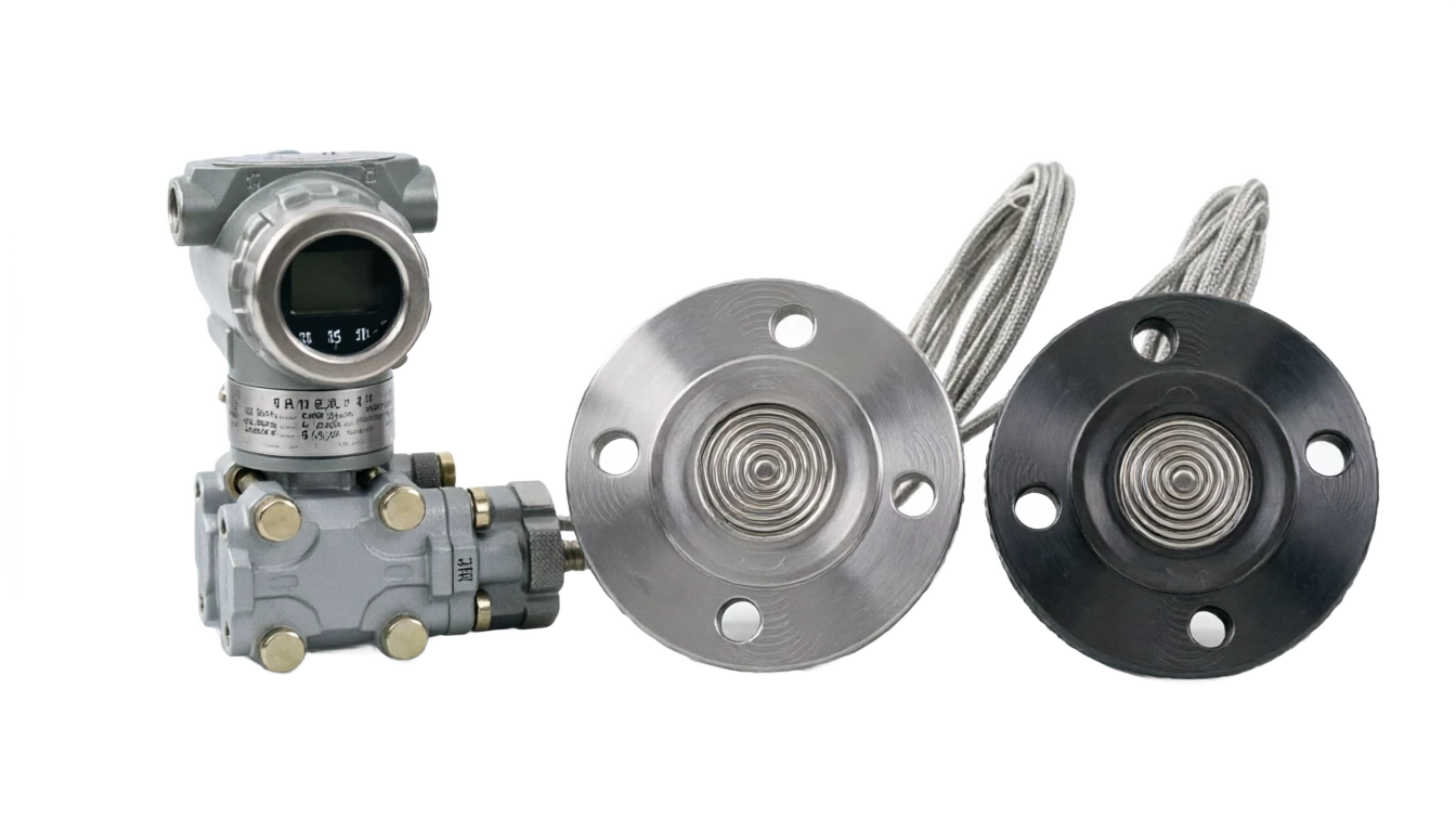
Bi-French diaphragm pressure transducer.

(a) Essentially, a differential transmitter, whose core measurement principle is that the pressure difference between the high pressure side and the low pressure side of the container is measured by ⁇ P, combined with the density (old) of the medium being tested and the acceleration of gravity (g), by formula H = ⁇ P / (old g) for the pressure vessel, the lower pressure side is applied to the atmosphere and the liquid position measurement is done only with a single side of the flang; For closed pressurized packagings, a double flange is required to collect pressure from the bottom (high pressure side) and top gas phase (low pressure side) of the packaging at the same time and to reduce the difference pressure values associated only with the height of the liquid column, thereby eliminating the effect of changes in pressure inside the container on the measurement of the liquid level. When the density of the medium changes with temperature (e.g. oil, liquefied gas), the temperature transmitter should be introduced to provide density compensation to improve the accuracy of the liquid conversion.

  1. 01

    1 High pressure side flanc + Separated film • Feel the bottom of the container / High pressure side pressure

  2. 02

    2 High pressure side fillings . Silicon oil, transfer of pressure through a catheter tube

  3. 03

    3 Low pressure side flanc + Separated film • Feel the top of the container / Low pressure side pressure

  4. 04

    4 Low pressure side filling. Silicon oil, which transmits pressure through a caustic tube.

Bi-French diaphragm pressure transmitter selection support

Provide survey missions, media and installation conditions and obtain product configuration advice.

Contact us
Bi-French diaphragm pressure transducer Technical Note

TECHNOLOGY & APPLICATION

Understand the principles, the exact selection.

The technical features and selection elements of the diaphragm pressure transmitters are understood from measurement principles to field applications.

01

TECHNICAL GUIDE

Overview

(also known as the bi-French differential transmitter or the tele-drive transmitter) is formed from the differential transmitter to form a remote transmission component, which is used mainly for liquid or depressive measurements of equipment such as closed containers, reaction pads, storage tanks, and is particularly applicable to routine pressure transmitters such as strong corrosive, high temperature, particles, crystallity, toxic, flammable and explosive.

This product is transmitted to the Fran for each side by a long-range transmission of pressure pressure (H) and low pressure (L) media, respectively, to the differential sensitivity element through metal plume and filling fluids (usually medical-grade silicon oil). The pressure sensitivity element converts the pressure differential from both sides to a standard industrial signal output, where the control system can convert the liquid position or interface position of the container in combination with the density of the medium.

This document will provide a systematic elaboration of the rationale, structure composition, comparison of strengths and weaknesses, application areas, technical parameters and selection guides, which will provide a reference for engineering design, equipment selection and on-site maintenance.

02

MEASUREMENT PRINCIPLE

Operating principle

2.1 The principle of differential measurement

Essentially, the differential deliveryer, the core measurement principle being: by measuring the pressure difference between the high pressure side of the container and the low pressure side ⁇ P, combined with the density (old) of the measured medium and the acceleration of gravity (g), by formula H = ⁇ P / (old g)

It is possible to convert to the height of the liquid level or the position of the two interfaces in the closed container.

2.2 Pressure transfer pathways

2.3 Description of liquid conversion

For constant pressure containers, low pressure side-to-air can be used for liquid position measurements using only single-side flanges; For closed pressurized packagings, a double flange is required to collect pressure from the bottom (high pressure side) and top gas phase (low pressure side) of the packaging at the same time and to reduce the difference pressure values associated only with the height of the liquid column, thereby eliminating the effect of changes in pressure inside the container on the measurement of the liquid level.

When the density of the medium changes with temperature (e.g. oil, liquefied gas), the temperature transmitter should be introduced to provide density compensation to improve the accuracy of the liquid conversion.

Page 3

Motion of work . Serial number / chainCross-reference
Serial numberLinkFunctional description
1High pressure side flanc + quarantine filmFeel the bottom of the container / the pressure side pressure
2High pressure side filling fluidSilicon oil, passing pressure through the capillary.
3Low pressure side flanc + quarantine filmFeel the top of the container / low pressure side pressure
4Low pressure side filling.Silicon oil, passing pressure through the capillary.
5Pair Sensitive ComponentConverting the pressure differential on both sides to resistance / capacitation change
6Zoom in on the circuits.Magnification, temperature compensation, linearity
7Output signal4–20 mA + HART / FF / PROFIBUS-PA
03

PRODUCT STRUCTURE

Product structure

3.1 Structure

The assembly consists of remote flange seals, capillaries and fill fluid, a differential-pressure sensing element, and an amplifier circuit. The remote assemblies on the two sides are normally symmetrical and interchangeable.

3.2 Typical structural diagram (text description)

The container, lower French, takes over the high pressure side long-distance transmission of the French (1) high pressure side film (2) high pressure side filling fluid (3) high pressure side cavity (4) high pressure side cavity element (5) low pressure side cavity sub-pipe (4) low pressure side filling fluid (3) low pressure side film (2) low pressure side transfer far French (1).

Standard industrial signals such as differential measurements, temperature compensation, linearization and signal conversion are performed within the main carrier by the end of the line output 4-20 mA + HART.

3.3 Remote transmission of French installation forms

Inserted French film (Extended Diaphragm) stretches into the packaging 50-200 mm side wall thin or avoids the internal wall corrosive layer, page 4

Process Frank (x2)

Main function: Connect to the container taking over Franc, under medium pressure31 Common material / Specification: 6L / Hapsy Alloy C-276/Cyber (as required)

Separatist film (x2)

Main function: Direct contact with media, conversion of pressure to micro-small shift Usual material / Specification: 316L / Haps C / tantalum / Monar / titanium

Filling fluid

Main function: Transfer pressure + Isolation medium + temperature compensation Common material / Specification: Silicon oil / HT Silicon oil / Fluorine / vegetable oil

Coward tube (x2)

Main function: Transfer pressure from remote to the main carrier 316 Usual material / Specification: L stainless steel shield / Zip PVC / stainless steel

Pair Sensitive Component

Main function: Convert ⁇ P into telecommunications, commonly used materials / Specification: Single crystal silicon pressure inhibition / Single crystal silicon capacitor

Zoom in on the circuits.

Main function: signal regulation, linearization, temperature compensation

Shell

Main function: Protection of internal components, provision of electrical interfaces Common materials / Specification: Aluminium alloy (spray)/ stainless steel 316L

Show Header

Main function: On-site display of measurements and diagnostic information Common material / Specification: LCD (optional backlight)

Connector End

Main function: Power and signal output interface Common material / Specification: Gold plating / Spring

Flush Flange

Structural characteristics: film is flat with the French end, no prominent

Entered Diaphragm

Structure characteristics:) film thrust into the container 50-200 mm typical application: the wall thin on the side of the container or the need to avoid the internal wall preservative layer

Health-level fast-loading card (Tri-Clamp)

Structural characteristics: Compliance with 3A / FDA health standards Typical applications: food, beverages, pharmaceuticals, biological products

Threaded

Structural characteristics: NPT/ BSP screws directly into the packagings Typical application: small calibre packagings, low pressure settings

Holding (Wafer / Cell)

Structural characteristics: Holding by piped Franks

04

TECHNICAL GUIDE

Analysis of strengths and weaknesses

4.1 Main advantages

It's a complete replacement for the extraction tube.

Specific: Double-side pressurization tubes, valve groups and condensers required for pressure deliveryers, saving material costs, lowering the system

Fits to the closed / pressurized perceivable perv

Specific: Long-range French can measure both upper and lower pressure in the container and can effectively eliminate the flow of pressure within the container and measure the liquid level

High-season, no leaks of wind.

Specific: Lang + Isolated film + Coin + Filled fluids with full seal structure, especially suitable for toxic, flammable and explosive

It's a strong corrosive film.

Specific: Precious metals such as Ha, C-276, tantalum, Monar, titanium, are selected to respond to almost any kind of corrosiveness

Anti-crystal, anti-cracked amino.

Specific: Surface is smooth and smooth in contact with the medium, with no pressure tube structure dead angles, which measure viscous, particle-bearing, condensable

Remote installation of flexible catheters

Specific: Customity (ranging from 1 to 10 m) and vector subjects can be far from high temperature, strong vibration or danger

The temperature compensation works well. It's a long way to go.

Specific: Passage between end and subject via filling fluids, relative stability of the cavity of sensitive elements, and ease of temperature supplementation

High accuracy of measurements

Specific: Typical precision ± 0.075% FS / ± 0.1% FS, with long-term stability better than 0.1% / year.

Smart diagnostic capability support H

Specific: ART / FF / PROFIBUS-PA bus, which achieves remote zero-pointing, self-diagnostic, predictive

Disadvantages and use restrictions

Higher prices due

Response response proposal: Containing a long-distance French component + caustic + filling system with greater overall cost than normal differential delivery

The catheter is vulnerable to mechanical damage.

Response response recommendation: Pygmy exteriors need to be protected from squeeze, convulsion radius too small, heat source baked or chemical corrosion

Filling fluid temperature drift filler

Response response proposal: Temperature changes lead to density changes, with the choice of the appropriate type of silicon oil or the following:

Zero drift two.

Response response proposal: Unsatisfactory length of side cavity tube, low height of installation, sun-skinned etc. all generate additional static pressure error

The response is slow.

Response response measures suggest that the transfer of caustic + filling fluids may be somewhat delayed compared to the direct installation of the transducer.

Maintenance Complicated

Response recommendation: The pharec and filling systems usually need to be replaced as a whole, with a relatively long on-site maintenance cycle.

Install height correction

Response response recommendation: Zero-point migration correction is required for precise input density when the carrier is installed at a high altitude that is not in line with the container Frank

Filling fluid spill risk

Response response recommendation: Filling fluids contaminate the detected medium (especially food/medicine scenes) when the tube or film seal is not in effect

05

APPLICATIONS

Application area

Extensive use of closed container fluids, interfaces, differential measurement settings in the following industries:

Page 5, page 6

Anti-rock oil, industrial convergence,

Typical application scenarios: distillation towers, vapour towers, acid-alkali tank liquid-level measurements; especially for viscosyl, PVC, alkyl, etc.

Oil fields, oil.

Typical application scenarios: ionizers, sink tanks, EDUs, free-water dehydration, water tankers, metering separators interface and liquid level

Power, boiler.

Typical application scenarios: vapour package liquids, high, low, condensed water tanks, deoxygens liquid measurements (high temperature, high pressure water vapour environment)

Metal and metal

Typical application scenario: co-casting of cold-water-flow, gas scrubber oxygen mask, acid sluice gauge.

Pharmaceuticals and foods

Steam boilers, bleaching towers, slurry pools, white water tower liquid level / interface measurements. Pile, storage tanks, CIP washing system, fermentation tank fluid level (sanitary Tri-Clamp apoly)

Environmental protection of water treatment

• Measurement of the liquid level of the steam boiler, bleaching tower, slurry pond, white water towers / interface.: Adding pots, sludge concentrate ponds, filter ponds / liquid level measurements; applicable to the glycerine-containing, particulate-containing sewage.

Chemical new materials

• Steam boilers, bleaching towers, slurry pools, white water tower liquid level / interface measurements.: polyurethane, glue, dye, catalyst slurry, high viscosity material fluid level / interface measurements.

Seamen on ships

• Measurement of the liquid level of the steam boiler, bleaching tower, slurry pond, white water towers / interface.: fuel tank, ballast water module, water desalination unit, liquid level measurement.

LUD / Liquefied Gas

Steam boilers, bleaching towers, slurry pools, white water tower liquid level / interface measurements. Ball cans, bedside cans liquid level measurements (deep cooling conditions need to be selected for cryogenic).

06

TECHNICAL SPECIFICATIONS

Technical Parameter Table

The following parameters are generic technical indicators for typical bi-French diaphragm pressure transmitters, and the actual product parameters are based on the plant out-of-plant data sheet.

Page 7

Technical parameter table · Parameter item / Specification parameterCross-reference
Parameters itemSpecification parametersRemarks
Measurement range (discretion pressure)0–1 kPa ~ 0–2 MPa(ΔP)Optional insulation, surface pressure, negative pressure
Quiet range0–16 MPa / 0–25 MPa / 0–40 MPaMaximum single-side pressure on high pressure sides.
Accuracy class±0.075%FS / ±0.1%FS / ±0.2%FSInclude linear, reversible, repetitive
Long-term stability± 0.1% FS/ yearSmarter than 0.1% / 5 years
Output signal4-20 MA + HART (two-line) optionalFF / PROFIBUS-PA / WirelessH
Electricity voltage10.5–45 V DC (Standard Type)Benz 10.5-30 V DC
Load capacity0–600 Ω(HART ≥ 250 Ω)It depends on the power voltage.
Process medium temperature40 ℃ ~ +150 ℃ (conventional silicon oil)+400 °C/ cryogenic - 196 °C (cooled)
Ambient temperature40 ℃ ~ +85 ℃Show the header -20 °C ~ +70 °C
Environmental humidity5% ~ 95% RHNo condensation
Ingress protectionIP65 / IP67 / IP68Depending on the location of the installation
Explosion protection markingExia ⅡC T6 Ga / Exd ⅡC T6 GbBased on GB/T 3836
Electrical connectionM20×1.5 / 1/2 NPTYou can choose the one that's gonna blow up.
Process Connection DN50/ NN80 / NN100 (HG/T / ANSI / JIS /DIN) Customised Special Specifications
Seal face formRF(Stand)/ FF(Stand)/ RTJ(Closed)Based on process needs
Isolation diaphragm material316L / HS C-276/ tantalum / Monnar / titaniumBased on the medium corrosiveness
Filling fluidSilicon oil (conventional) / HT Silicon oil / fluorine / vegetable oilFood Level Optional FDA / 3A Certification
Capillary length1.5 m / 3 m / 5 m / 7 m / 10 mThe length of the capillary tube should be consistent.
Coin tube material316L stainless steel + PVC protective / stainless steel weavingThe blast site is open for stainless steel fittings.
Response time≤ 200 ms. (Destructed 0 — 60 s)Electrical and mechanical blockages
WeightAbout 5-10 kg (excluding Faraway Franc)With the French specification and the length of the casket
Body materialAluminium alloy (spray)/ stainless steel 316LPreservative grade options
Communications agreementsHART 7 / WirelessHART / FF / PROFIBUS-PAOptional Smart Diagnosis
07

SELECTION GUIDE

Select Table

This section provides an option reference for three dimensions, "discretion scale", "application scenario" and "discretion French installation", to facilitate rapid positioning models by engineers during the design phase of the project.

7.1 Table of options for the range rate

7.2. Select the format by application

7.3 Expedition French installation schematic

Page 8

7.4 Frequent French specification checklists

Page 9

Selecting table . The quantum code / the margin rangeCross-reference
The quantum code.The range of pressureQuiet rangeTypical applications
RC-010–0.2 ~ 1 kPa0–16 MPaConstant pressure tanks, slurry slots
RC-020–1 ~ 6 kPa0–16 MPaSeal container low liquid level
RC-030–6 ~ 40 kPa0–16 MPaReaction fluids, interfaces
RC-040–40 ~ 200 kPa0–25 MPaModerate pressure container fluid level
RC-050–0.2 ~ 1 MPa0–40 MPaHigh pressure containers, boiler bags
RC-060–1 ~ 2 MPa0–40 MPaSuper-high pressure reactor
RC-V ±0.5 kPa / ±2 kPa / ±10 kPa 0–16 MPaInterface, traffic differential
RC-H 0~10 ~ 100 kPa (highly static)) 0–40 MPaHigh pressure gas interface
ApplicationsMedia FeaturesSuggested selection elements
Condensed container liquid levelIt's a little corrosive.316L film + conventional silicon oil + pyranc
High pressure reaction padsPressure 6-16 MPa, high temperatureHigh still pressure type + high temperature membrane + Ha, C-276
Acid storage tanksCorrosive acidtantalum / Hadium C film + PTFE liner + fluorine
Boiler bag liquid levelHigh temperature, high pressure water saturation/steamCondensate + high temperature silicon oil + one-sided remote transmission
Food / MedicineHealth level, CIP requirementsTri-Clamp Fast + Sanitary Silicon (FDA)
Oilwater separatorsTwo interfaces, small density differenceHigh precision (0.075%)+ Interface algorithm
LNG / LSD tankDeep cold - 196 °CCold + stainless steel catheter + cryogenic filler
Oil / tarHigh viscosity, crystallityInsert long-distance transmission of Franc + large DN80/DN100
Corrosive fumesSO / HCl / Wet FungH.C.-276 film + embalming shell
Catalytic slurryContaining solid particles, readily available for depositionHemphran + Large-sized film + Counterbow Interface
Form CodeMounting configurationSuitable operating conditions
F-FLFlush FlangeThin, crystal-friendly medium
F-EXInserted FrenchPackaging side wall thin, embalming layer
Selected Table . F-TR / Tri-Clamp Health LevelCross-reference
F-TRTri-Clamp Health LevelFood, beverages, pharmaceuticals
F-THSniff Connection (NPT/ BSP)Small caliber, low pressure containers
F-WAWafer holderPipe traffic differential
F-CUCustom FrankSpecial Standard / Anisode
Specification DesignatorNominal pipe sizeNominal pressureSeal face form
F-50ADN50 (2")PN16 / 150 lbRF (Darling)
F-80ADN80 (3")PN16 / 150 lbRF (Darling)
F-100ADN100 (4")PN16 / 150 lbRF (Darling)
F-50HDN50PN40 / 300 lbRF / RTJ
F-80HDN80PN40 / 300 lbRF / RTJ
F-50CDN50PN100 / 600 lbRTJ
F-Tri50DN50 (2")Health levelTri-Clamp, fast-load.
F-Tri80DN80 (3")Health levelTri-Clamp, fast-load.
08

SELECTION GUIDE

Selection of guidance and attention

8.1 Selective Steps

8.2 Installation and use of attention

  1. 01

    The length of the catheters on both sides should be consistent to avoid the miscomposition of static pressure due to different quality of filling fluids.

  2. 02

    The catheter should avoid the heat source baking, vibration areas and chemical corrosive environments.

  3. 03

    The catheter bending radius should be ≥ 150 mm to avoid bending and flattening and blocking the filling tunnel.

  4. 04

    The catheter should be fitted in a manner that avoids moving areas of personnel and is protected by metal troughs.

  5. 05

    The main transducer must be moved zero points when the installation height of the carrier is above 0.5 m.

  6. 06

    When measuring vapour or boiling media, a condenser shall be installed in front of the long-distance transmission of French.

  7. 07

    Long-distance French pre-installation check for gasket specifications, and the bolts are equally tightly fixed to avoid single-side stress.

  8. 08

    Direct contact with the amputated film surface by hard matter is strictly prohibited in order to avoid film distortion.

  9. 09

    The shipment should be preceded by a zero and full mass validation, with the use of the HART hand-manufactor to form the state remotely.

  10. 10

    The pressure valves should be shut down for long periods of time, power cut, and protection fluids filled if necessary.

  11. 11

    The hazardous site wiring should meet the blast-proof level requirement, with a single end of the cable shield.

8.3 Maintenance and troubleshooting

Page 10 - End of Document -

Selected guidance and attention . Steps / Key elementsCross-reference
StepsKey elements
Step 1 . Clearly measured objectRecognized medium name, density, temperature, pressure range, corrosivity, viscosity, particle or crystallity
Step 2 . Calculate the differential pressure rangeCalculates the ⁇ P = old g Hmax based on the maximum density of the medium and the liquid level, and selects the appropriate range.
Step 3 . Confirm static pressure levelSelect the corresponding static pressure level (16/25/40 MPa) based on the maximum working pressure of the packaging.
Step 4 Selecting film and filling fluidsSelect the film and filling fluids based on the medium corrosivity, temperature range.
Step 5 Selecting the long-distance French formSelect the pyramid/ insert/ sanitary/ screw connection according to the container interface, the medium flow state.
Step 6 . Select the length of the capillaryThe length of the catheter (both sides equal) is determined by the location of the main carrier installation and distance from the remote end.
Step 7 . Confirm output signalSelect 4-20 maA + HART or FF/ PROFIBUS-PA bus protocol.
Step 8 Safety and protectionThe blast and protection levels are selected according to the hazard area on site.
Step 9 Zero Migration AmendmentThe altitude of the transvestite is determined to be different from the distance French installation and, if necessary, the zero-point migration.
Selection guidelines and attention · Common failures / Possible causesCross-reference
Common malfunctionsPossible causeSuggested measures
Output constant 4 maA or 20 maAPower supply abnormal / connection opening / film fractureCheck the power supply, check the circuits, watch the film.
Output does not match liquid levelScale / Density Settings Error / Zero FloatRe-mark, fix density, re-route zero points
Output small drift for a long timeCough tube subject to temperature / Filling fluid changeCheck the catheter and evaluate the filling model.
Selective guidance does not match the note · static pressure error is wide / length of cavity on both sides / installation height differenceCross-reference
The static pressure is wide.The length of the cascades on both sides is not consistent / the height difference is installedReplacement of long-haired tube and re-drive of zero points
Communication FailedLoaded electrical resistance < 250 / interference / protocol versionCheck load resistance, shielding, protocol match.
Filling fluid leakSpectrum rupture / caustic break / interface leakChange the remote components, strengthen the interface
Response response is clearly lagging behindThe blocker set too big / the filling fluid is too stickyReduce electrical blockage, replace low viscosity filling fluids