PRODUCT TECHNOLOGY

Process signal simulation

Operating principle

Process signal simulation.

(a) The detected signal is converted to the electrical relay network by input point entry, choosing different front-end circuits according to the type of signal: the current current is converted to voltage by 10 precise sampling of the current; (b) The volt/mg signal instrument amplifier (INA) amplification and filtering; (b) Resistance measurements are based on a four-line constant flow method, inspired by a constant flow source of 0.5 ~1 MA, without pressure-down error on the wire-retarded electrical resistance; Frequency signals are measured by the Schmid trigger integer and the delivery counter. The total adjusted simulation was sampled by the 24-bit ⁇ -synthetic ADC and revised by CPU calibration factor for each quantity (multipoint temperature reimbursement) to eventually show the project value. ±0.01% plus 2 words to measure accuracy to read. The core of the output channel is 16-20 bit precision DAC

  1. 01

    1 • Task preparation • Downloading from management software to verify tasks or manual tasks (bits/ quantities/ points) • Verifying schemes

  2. 02

    2 . Wire recognition . Identification of circuit type (two-line / four-line / active / passive) and selection of the corresponding ender . Correct connection

  3. 03

    3 · Safety isolation · Disconnect the loop from the DCS isolation barrier or place it in bypass. Post a “Calibration in progress” warning and verify isolation.

  4. 04

    4 . Backway Power . Start 24 V LOOP POWER, string in and read the carrier's static current.

Process signal simulation calibration machine selection support

Provide survey missions, media and installation conditions and obtain product configuration advice.

Contact us
Process signal simulation machine Technical description

TECHNOLOGY & APPLICATION

Understand the principles, the exact selection.

From measurement principles to field applications, the technical features and selection elements of the process signal simulation machine are understood.

01

TECHNICAL GUIDE

Overview

1.1 Product definitions

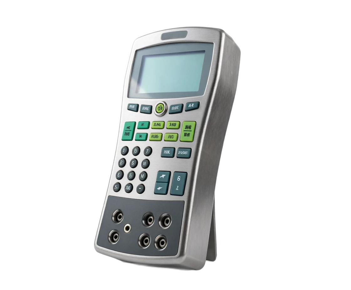
(also known as the Multifunctional Process Validator) is a portable verification device covering all standard telecommunications numbers for industrial processes. It combines "sign source" with "sign table" to "sign chart" as one: in the source mode, it can accurately export current currents (0~24mA), voltage (0~10V), millivolt, frequency, resistance and even simulated heat resistance/thermal electrocution (HTE) signals at the given value, for the verification of transformation transmitters, monitors, logs and DCS / PLC input cards; In table mode, all the above-mentioned signals are measured with high precision and are used to verify the authenticity of the signals in the field; The two are superimposed, together with the built-in 24 V-return power and the HART communication, and complete the full validation and diagnosis of a process circuit independently.

Unlike a single function's temperature proofing simulator (No. 38, covering only RTD/TC temperature signals) or pressure verification (No. 36, covering pressure parameters only), process signature verification seeks "full-parameter coverage" - a meter can respond to multiple verification tasks such as 4-20 max, thermoelectric doll/thermal resistance temperature signal, frequency/reverse signal, valve position feedback, and is a platform-level tool common to instrumentation workshops and WIP teams. High-end models (e.g. Fluke 754, Beaumex MC6) are more integrated into the full process closed loop of HART / FF / PA bus communications and documentation auto-checking (Documenting Calibrator) to achieve "task-on-site execution-data upload-certificate generation".

1.2 Core values

The task of integrating the previously required signal generator, precise digital mass gauge, standard electrical block, straight current steady pressure source, HART handheld, 5 ~ 6 equipment into a handheld device for 1 ~ 2 kg, and reducing the verification time of a single carrier from 30 ~ 60 min to 10 ~ 15 Min in the traditional combination. For factories with hundreds of thousands to tens of thousands of process meters, the rotation of the control cycle saves thousands of working hours a year, while eliminating artificial errors resulting from the discrepancies between the load and the handling of multiple equipment. Documentation models also automatically archive the verification data and meet ISO 9001/IEC61511 compliance requirements for periodic instrumentation verification records that are traceable.

1.3 Evolution

Table 1 - 1 Process signal simulation.

1.4 Boundary with adjacent verification equipment

Table 1-2 Process signal simulation and adjacent equipment capability boundaries

1.5 Major manufacturers

Table 1-3 Major manufacturers and representative models

Overview · Phase / PeriodCross-reference
PhasePeriodTechnical characteristicsRepresentative form
11970s-1980sSignal generator + Numbers are separated by table, manually swapping the circuitDesktop Signal Source & DMM
21990sMeasure / Source Integrated Handheld appearance, 0.05% accuracyFluke 705 / Beaumex MC5 Generation
32000sAdd RTD/ TC fraction simulation, HART communication, step autocheckFluke 744 / Beamex MC5-IS
42010s To dateDocumentation Autocheck, Double-channel Sync, Touch screen, Bluetooth App, FF/ PA busFluke 754 / Beamex MC6 / ConST 820
· Equipment / Overriding ParametersCross-reference
EquipmentOverwrite ParametersTypical precisionPositioning
Process signal simulationmA / V / mV / Hz / Dot/ RTD / TC All Signals±0.01%~0.02%Full Parameter Platform, Universal Power Protection
Temperature Validation EmulatorRTD / TC Temperature Signals Only±0.1~0.5 ℃The temperature secondary instrument is special, and the price is low.
Pressure (vacuum) calibrationPressure / Vacuum parameters (includes occurrence)±0.02%~0.05% FSPressure transmitter field verification special.
Dry furnace / Constant TemperatureReal temperature field±0.1~0.5 ℃Sensor Body (one widget) Validation
HART HandicraftDigital Communications Groupe OnlyNot involving a volumeTransponder parameter configuration and diagnosis, not accurate
Overview · Vendor/ CountryCross-reference
VendorCountryRepresentative ModelCharacteristics
Fluke.United States754 / 726 / 753Documentation auto-checker poles, HART high integration, largest stock in petrochemical industry
BeamexFinlandMC6 / MC6-IS / MC2Double channel + touch screen, fully certified, and best ecologically perfected with calibrated software
AdditelUnited States / China780 / 223High value for money, overwhelming HART, Chinese-friendly
GE / Druck (Druck)United KingdomDPI 612 / DPI 611Pressure + Composite verification of telecommunications, commonly used in aviation measurement
WIKAGermanyCPH7600 / CPH7650Pressure and telecommunications. Industrial reputation.
Const (Const)China810 / 820 / 313High-end representation of national production, pressure + telecommunications + HART, full coverage, with clear price advantages
Time ElectronicsUnited Kingdom5025 / 5075Desktop multifunctional validation source, laboratory measurement site
Trans-Hand/ AZ/ Victory/ EuretJapan/ ChinaCA11 / VC14 / UT780Economic product lines for small and medium users
02

MEASUREMENT PRINCIPLE

Operating principle

2.1 Signal measurement principles (table pattern)

(a) The detected signal is converted to the electrical relay network by input point entry, choosing different front-end circuits according to the type of signal: the current current is converted to voltage by 10 precise sampling of the current; (b) The volt/mg signal instrument amplifier (INA) amplification and filtering; (b) Resistance measurements are based on a four-line constant flow method, inspired by a constant flow source of 0.5 ~1 MA, without pressure-down error on the wire-retarded electrical resistance; Frequency signals are measured by the Schmid trigger integer and the delivery counter. The total adjusted simulation was sampled by the 24-bit ⁇ -synthetic ADC and revised by CPU calibration factor for each quantity (multipoint temperature reimbursement) to eventually show the project value. ±0.01% plus 2 words to measure accuracy to read.

2.2 Signal simulation output principles (source mode)

The core of the output channel is 16-20 bit precision DAC and discharge/power level: the power output is buffered by the DAC directly via low noise; (a) The current output (0~24 ma) is converted from a DAC-set value to a constant current (Howland circuit or power discharge closed loop) and can withstand up to 1 k return load (relative to 24 V to voltage); The electrical resistance output is balanced by electronic resistance networks and the server, which can be as accurate as ± 0.02 times by internal measurements of actual voltage reduction and current, real-time adjustment of equivalent resistance; (a) Thermal electromechanical signature is formed by the millivol output superimposer plus cold end to compensate for the temperature electrical motion; Frequency output is directly synthesized by the MMU timer, and the range and wave shape can be set.

2.3 Second-line circuit and transducer simulation

Yeah. 4 ~ 20 MA 2-line circuits, instruments provide three modes of participation

First, the LOPPOWER model, which incorporates 24 VDC isolated power streams attached to the circuit, while measuring the transmission of electricity from the carrier, and one equipment completes the power supply and reading; Second, the transducer simulation (inactive imitation) model, where the instrument as a "false transducer" absorbs circuital currents and adjusts them to set values for the validation of DCS cards, safety fences and monitors; Third, active output mode, which injects 4-20 mA directly into passive loads (records, indicators). Three modes cover all the lines in the back-to-back check of the "source side" and "watch side."

2.4 Conversion of temperature scales

Instrumentation contains a split table of IEC 60751 (Pt100 et al. 8 thermal resistance) and 10 IEC 60584 (S/R/B/K/N/E/J/T). When measured, the resistance / mvolt is inverted to temperature by the fraction function; The target temperature is counted as a resistance/mPV value at the time of output, where thermal voltage output is also superseded with cold end to compensate for voltage (inline temperature sensor ± 0.2 ~ 0.5 °C, which can close the CJC outer ice point at a high accuracy). The fraction is achieved by a 1 °C interval check + linear interpolation, which is much less than 0.1 °C for the reverse of the conversion residue.

2.5 HART Digital Communications

Select the model for HART Modem to connect the Bell 202 FSK signal (1200 Hz / 2200 Hz superimpose on 4 ~ 20 ma) to the current loop, press HART 5 / 6 / 7 protocol rounder: Read bit numbers, ranges, units and output currents, lower load process modifications and resistance parameters, read from diagnostic status. This allows "sign checking" to be synchronized with "parameter verification" in a single connection, and HART current readings are comparable to analogue measurements and are used to detect transmission output-level failures.

2.6 Step / Slipper and Documentation Automatic Validation

Source mode supports automatic step (0%/25%/ 50%/ 75%/ 100% or custom points, 10~60s per point) and continuous slopes (set rate rises/ drops). In conjunction with the dual channel "One source " (A channel output standard signal, B track measurement is tested for export), the instrument automatically records input output, calculates the error/return error/repeat error/repeal error and determines whether it is valid or not. Documentation models can be pre-downperformed from the validation management software (e.g. Beaumexbrix, FlukeDPCTrack2), and the data are returned to the site by guiding the process and automatically generate original records and certificates that match the protocol.

2.7 Workflows

Table 2-1 Process signal simulation 8 Step workflow

The working principles . Steps / linksCross-reference
StepsLinkOperation contentOutput
1Mission readiness.Downloading from management software to verify tasks or manually (bits/ process/ points)Validation Scheme
2Connect.Identify the type of circuit (two-line/ four-line/ active/ passive) and select the corresponding endorGetting it right.
3Safe isolationDisconnect the back road with the DCS fence or sideways, and put on a "check-in" sign.Isolation confirmed.
4Loop powerStart 24 V LOOP POWER, string back and read the transvestite static currentStatic current value
5As-Fund VerifyStep point output standard signal, synchronized record of detected carrier outputPre-school data
6AdjustmentOvertime adjusted output via HART or / Quantification buttonAdjusting Records
7As-Left VerifyRepeat step check, log adjusted dataPost-school data
8Restore and ArchiveReconnect, confirm circuits are normal, data feed software generation certificateCould not close temporary folder: %s
03

PRODUCT STRUCTURE

Product structure

3.1 Composition of the whole machine (12 components)

Table 3-1 Process signal simulations Composition of 12 components

3.2. Channel structure

The two-channel model uses A / B, two separate full-functional channels, each containing complete input adjusters and output levels, which can be set to "measure" or "output" separately, forming a "one source" combination: for example, A Channel to output temperature transcipher Pt100 analogue signal, B Channel to measure transceivers 4-20 maA output, single loop to complete input-output characterization of the entire transvestite. The single-channel economy is based on switching the endpoint to perform the same task, with a reduction of efficiency of about half.

3.3 Structured forms classification (6 categories)

Table 3-2 Structured forms classification

Engineering plastics case

Functional description: Handheld shell, fall-proof side, protection level IP54 ~ IP67 Critical feature: 1 m falls survives

Display

Functional description: 3.5 ~ 5 inch colour touch / point array liquid crystal, synchronised display of two channels Key properties: readable in sunlight

Keyboard

Function description: Numerical + Functional key, actionable with gloves Key properties: Silicon gel keys

Enter the modem

Function description: Scale to Switch relay + instrument amplifier + Filter network Key properties: Multi-Communication Frontend

24-bit ADC

Functional description: ⁇ - ⁇ model conversion, full range 0.01% Class Key properties: temperature drift < 5 ppm/°C

DAC and Power Level

Function description: 16~20 bit numeric model conversion + voltage-controlled current source / discharge buffer Key characteristics: comply with voltage 24 V

Loop power supply

Functional description: Separation 24 V DC, restricted flow protection 25 MA Key properties: short circuit self-recovered

Connector End

Function description: Enter a stand-alone end to the power source/ return to the circuit, security plugin Key properties: error-proof plug-in design

HART Modem

Function description: Bell 202 FSK modem (selection), HART 5 / 6 / 7 Key properties: enders with simulation

Master MPU

Functional description: ARM kernel, running fractional meters, step control and documentation task engine Key properties: low-capacity design

Battery and power management

Function description: Lithium ion batteries 12~20 h, USB / Adaptor charge

Storage and communications

Function description: 8 GB storage + USB/ Bluetooth interface, tasks and records management Key properties: CSV / PDF export

Category

I'm not sure if you're gonna be able to get a good look at it.

Handheld Line

0.8~1.2 kg, fully functional but with few accesses Fluke 707H / ConST 311 Daily patrols and simple circuits

Handheld dual channel

1.2 ~ 1.8 kg, one source, touch screen Fluke 754 / Beaumex MC6 adapter verify main power model

Documentization

Job Download / Data Relay / Certificate Generation Fluke 754 / MC6 + Plants with Retroactive Requirements for Compliance

Ben-Ann's blastproof.

ATEX / IECEx / CNEx authentication, Energy Limiting Beamex MC6-IS / ConST 820-IS petrochemical / Gas blast-proof area

Desktop Multifunctional

0.01% above level, multiple access routes, municipal electricity 5025 / Red flag 9000 series

Pressure complex

Internal pressure module interface, electrical + pressure co-read Druck DPI 612/ / M6-P Mixed pressure with telecommunications

04

TECHNICAL GUIDE

Advantages and disadvantages

4.1 Advantages

Table 4-1 Process signal simulation 8 Great advantages

4.2 Disadvantages and responses

Table 4-2 Process signal simulation 7 shortcomings

4.1 Advantages

All Parameters Overwrite

Note: A process signal that covers the mA / mV / V / Hz / / RTD / TC, replaces 5 ~6 single devices

One of the sources of measurement

Note: Both signal and signal detector, complete the output verification of the entire carrier input and output along with the two-channel monocades

Backway power supply integration.

Note: Internal isolation 24 V power source, exemption from external powerbox, double-line circuit check.

Autostep and document

Note: 0~100% Step / Slipper Auto-execution, As-Fund / As-Left data records, certificate automatic generation

HART One

Note: Simulation verification synchronized with numerical grouping, HART current and analog readings cross-check

Portable efficiency

Note: 1-2 kg handheld, single transmitter verified 10-15 min, 2~3 times faster than the combination device

Precision is reliable.

Note: 0.01% ~0.02% Level, meet industrial transporters ( 0.075% ~0.2% Level) 1 : 4 Check accuracy ratio requirements

Environmental adaptation

Note: IP54~IP67 protection, 20~50 °C work, this Ant-type is ready to enter blast-proof area

4.2 Disadvantages and responses

High prices

Impact: High-end documentizer 5 ~ 150000 CNY, which is 3 ~ 5 times the single function calibration Response: Slotting by frequency of mission, non-recurrent user options economic

Can't learn the sensor body.

Impact: Telecommunications simulation cannot replace temperature / pressure real amount Respond: a dryer-coated furnace / a constant temperature cell / pressure standard unit consists of a tool chain

Operation Complicated

Impact: Multiple functions lead to deep menu levels, training cycle 1-2 weeks Response: use task downloads to anchor complex processes into guide execution lines

Battery Limit

Impact: Shorter cryogenic continuation, circuit power back + HART time power acceleration Response: backup battery / mobile power source, full pre-mission

Inter-channel interference

Impact: Inadequate separation of cheap machine-type dual-channels, detection of sources, interlocking of sources Response: choice of quarantine route design, or verification of two single-channels

Limited protocol coverage

Impact: FF / PA / Profibus requires a specific tool or high-end selection outside of HART Response: Checking list according to the current bus-based pattern

Software binding

Impact: Documentation functions rely on the vendor's private management software, which is closed according to format

05

APPLICATIONS

Application area

5.1 Typical application scenario (12 categories)

Table 5-1 Process signal simulation 12

5.2 Industry application matrix

Table 5-2 Industry application matrix

Pressure / differential sender verification

Verify object: Two-line 4~20 MA Transmitter Group Signal Group: Backway Power + Current Measurement + HART Moderation

Temperature Transmitrator Validation

Verify object: Integrated Temperature Transmitters (RTD/ TC input) Signal combination: RTD / TC Simulation Output + Electricity Measurement

DCS / PLC input card testing

Verify object: AI card channel Signal combination: mA / V / mV / RTD signal injecting + read-number matching

Check the monitor and log recorder

Verify object: On-site indicator / Paperless recorder Signal combination: active maA output injected

Secure lock-back route validation.

Verify object: SIS Return / Alert Seter Signal combination: Accomplishment action value and a compound value for an ultra-regulator signal

Executor / Valve Locator Debug

Verify object: E-Air locator / Valve Feedback Signal combination: 4~20 MA output + Location feedback measurement

Security fence / separator verification

Verify object: Signal separation fence / This fence Signal combination: Enter output double-end survey source

Secondary flow check

Verify object: Flow Accumulation / Temperature Compensation Unit Signal combination: Frequency (pulse)+mA + RTD combination signal

The frequency transformer and the speed loop.

Verify object: Retrospective display / variable frequency given signal combination: frequency output (0.1 Hz~10 kHz)

Reweight and Response Road

Verify object: Responsive signal modem (mV level) Signal combination: millivol source output

Instrumental inspection and failure diagnosis

Check object: On-site back-tracking check for authenticity

Measurements set-up kit

Validation object: On-site check as 0.01% standard device Signal combination: with pressure standard / dry furnace composition check system

Petroleum chemicals

Main verified object: Pressure / Temperature / Flow Transmitter, SIS Return Path Usage: blast-proof area operation, certificate compliance high Recommended configuration: This Annified Document (MC6-IS / 820-IS)

Electricity

Main verification object: Hotman DCS card, transducer, implementer Usage feature: crew overhaul period centralized verification Recommended configuration: two channel documentation type

Gas / Gas field

Main verify object: Remote metering, pressure-reducing station meters Usability characteristics: field-free, high temperature differential Recommended configuration: this Ant+ long-carrying battery

Metallurgy / Building Materials

Main verification object: kiln temperature meters, flow units Usability characteristics: high temperature dust environment, high frequency

Pharmaceuticals/ Food

Main verify object: Clean Area Temperature / Pressure Instrument Usage: GMP Record Integrity and Audit Tracking Recommended Configuration: Documentation + Software Management

Water treatment / Environment

Main verify objects: online analyser, pH / soluble oxygen sender Usage characteristics: budget sensitive, variable parameters Recommended configuration: economy-type full-function machine

06

TECHNICAL SPECIFICATIONS

Technical Parameter Table

6.1 Technical parameters for the whole machine (22 Divisions)

Table 6-1 Technical parameters for the whole machine

6.2 Comparison of accuracy of signal types

Table 6-2 Measurement of signal type / Output accuracy

Technical parameter table . Serial number / parameter itemCross-reference
Serial numberParameter ItemTypical valueRemarks
1Current measurement range0~24 MA (basic range)With 4~20 maA and 0~10 / 0~20 maA formula
2Current measurement precision±0.01% Reader + 2 Word1 Year indicator, linear and temperature drift combination
3Current Output Range0~24 mARespond to voltage ≥ 24 V, load ≤ 1 k
4Pressure measurement/ output0~10 V / -10~100 mVPrecision ±0.01% Read + 2 words
5Resisting Measurement / Output0~3200 ΩFour-linear measurements, 0.01 times resolution
6Frequency measure/ output0.1 Hz~50 kHzRange 0-10 V square wave, ratio available
7Thermal Retardation Depression SpectrometerPt10 / Pt50 / Pt100 / Pt200 / Pt500 / Pt1000 / Cu50 / Cu100IEC 60751 / JJG 229
8The thermoelectric doll imitation fractional.S / R / B / K / N / E / J / T / C / WReIEC 60584 / JJG 351
9Temperature precisionRTD ±0.1~0.2 ℃ / TC ±0.3~0.5 ℃The fraction number is related to the time frame
10Cold end compensation accuracyAutomatic CJC ±0.2~0.5 °CSupport for the shutdown of the outer ice point.
Technical parameter table . Serial number / parameter itemCross-reference
Serial numberParameter ItemTypical valueRemarks
11Loop power supply24 V DC isolation, restricted flow 25 MAShort-circuit protection and self-rehabilitation
12Number of channels1 or 2 full functionality channelTwo channels support one source.
13Access quarantine.≥ 50 VHigh-end machine ≥ 300 V
14Step function2~11 point custom, presence 10~60 sIncluding 0/25/50/75/100% shortcut mode
15Slipper functionRate 0.01~99 mA/min availableFor continuous response testing
16HART CommunicationsHART 5 / 6 / 7 (selection)Round / Overmount / Group / Diagnosis
17Data Storage≥ 8 GB, ≥ 100000 RecordAs-Fund / As-Left-Stocked Storage
18Communication interfaceUSB / Bluetooth / RS-232Supporting tasks downloading and data return
19Display3.5~5 inch colour touch / dotting LCDDouble Channel Same Screen
20Battery continues.Lithium 12-20 h (typical)USB / Adaptor Charge 3~4 h
21Protection and fallIP54~IP67,1 m fallingBen Ang by ATEX / IECEx
22Operating environment20 ~ 50 ℃, Humidity ≤ 90% RH No CondensationStorage - 40~70°C
Technical parameter table · Signal type / Typical scaleCross-reference
Signal TypeTypical scaleMeasurement accuracyOutput AccuracyResolution
Direct current.0~24 mA±0.01% RD + 2 Word±0.01% RD + 2 Word0.001 mA
Direct current voltage0~10 V±0.01% RD + 2 Word±0.01% RD + 2 Word0.1 mV
Straight-flank.10~100 mV±0.02% RD + 3 word±0.02% RD + 3 word0.001 mV
Electrical resistance0~3200 Ω±0.02 Ω±0.02 Ω0.01 Ω
Thermal electrical resistance (Pt100)200~850 ℃±0.1~0.2 ℃±0.1~0.2 ℃0.01 ℃
Hottelescope (K type)200~1372 ℃±0.3~0.5 ℃±0.3~0.5 ℃0.1 ℃
Frequency0.1 Hz~50 kHz±0.005% RD±0.005% RD0.01 Hz
Pulse Count0~999999±1 pulses—1 pulse
07

SELECTION GUIDE

Select Table

7.1 Type by functional slot (4 tranche)

Table 7-1 Functional slotting format

7.2 Select object by verification (Category 6)

Table 7-2 Selected types by verification

7.3 Select type by precision slot (3 tranche)

Table 7-3 Precision slotting formula

7.4 Selected types by communication and data management (5 tranches)

Table 7-4: Selected Communications and Data Management Tables

Selective Table . Slotting / Signal CapabilityCross-reference
TrailSignal capabilityTypical precisionPrice RangeApply User
The economics.MA / V-detection source + circuit power±0.05%0.3 ~ 10000 CNYSmall business inspection, simple return, road check.
Standard Full FunctionmA / V / mV / Ω / Hz / RTD / TC±0.02%1 ~ 40000 CNYWatch team is on daily protection.
DocumentizationFull signal + double channel + HART + task management±0.01%~0.02 %4 ~ 100000 CNYCompliance at large and medium plants
Ben/ complex high endDetonation authentication or pressure compound + FF / PA±0.01%8 ~ 150000 CNYZero-chemical blast/Measurement Centre
Select Table . Verify Object / Required FunctionsCross-reference
Instruments under calibrationRequired FunctionsRecommended ChannelsAdditional recommendations
Double-line pressure / differential transmitterBackway power + MA measurement + HARTOne channel is fine.Double channel if you enter the same temperature at the same time
Temperature Transmitter (RTD / TC input)RTD / TC Simulation + masculinityDouble channel (one source)Check the fraction number and the range overlay
DCS / PLC AI cardMA / V / mV / RTD Multi-Communication OutputSingle channelPrepare to turn the signal.
Safety fence/ separatorDouble-end survey source + circuit powerDual ChannelsNote this Angle Match
Executor / PositionerMA output + feedback measurement + valve testDual ChannelsOptional 24 V power field meters
Flow ImpressorFrequency / Pulse + ma + RTDDual ChannelsCheck pulse bands and patterns
Selective table · Precision slotting / Typical indicatorsCross-reference
Precision SlottingTypical indicatorsPrecision level of the detectable objectTrace Method
Field level±0.05%0.2% Industrial Tables below ClassAnnual inspection or matching
Working level±0.02%0.075% Level smart transporterAnnually, the metering lab will be certified.
Standard Level± 0.01% and higher0.02% ~0.05% class high-precision senderAs standard instrument, a test is required
Selective Table · Data Capability / Functional DescriptionCross-reference
Data capacityFunction DescriptionApplication of compliance scenarios
Manual RecordingLive readings, manual filling out of formsNo mandatory recording requirement
Local StorageResults storage instrument, after USB export CSVInternal quality management
Tasks are performedVerify program download, wizard executionMulti-Performance Harmonization Process
Selective Table · Data Capability / Functional DescriptionCross-reference
Data capacityFunction DescriptionApplication of compliance scenarios
Document & Closed RingAs-Fund / As-Left Full Record + AutoCertificateISO 9001 / IEC 61511
System-level integrationInterfacing with the Enterprise Asset Management System (AMS/CMMS)Digital validation of smart factories
08

SELECTION GUIDE

Selection Guide

8.1 Ten-step selection process

Table 8 - 1 Ten-step selection process

8.2 Comparison with neighbouring programmes

Table 8-2 Comparison of three verification options

8.3 Selected decision tree (10 rows)

Table 8-3 Selected decision tree

8.4 Installation and use of attention (12 articles)

Table 8-4 Installation and use alerts

8.5 Maintenance cycle (6 items)

Table 8-5 Summary of maintenance cycle tables

Process signal simulation is based on "All Signals One + Two Channels One Source + Backway Power + HART Communication + Documentation Automatic Validation" as the technical core, compressing 5-6 single functionality devices into a handheld, which is a platform-level tool for process instrument protection and compliance verification. It covers the full "second instrument" verification mission by telecommunications, but the sensor-book medical examination is still required for dry furnaces/heating cells/pressure standard units, which form the top layer of the three-storey verification tool chain "one element-second instrument-full parameters". The selection follows the decision of the "list of objects, signal cover channel numbers, 1:4 accuracy ratio, ⁇ blast-proofing, ⁇ data compliance environment, ⁇ trace source, ⁇ full life cost" and achieves the optimal balance between investment and capacity.

Selection guide · Steps / ContentCross-reference
StepsContentsPoints
1Checklist of ObjectsType of carrier / signal formula / quantity / accuracy level, creating demand baseline
2Confirm signal overlayPush the required signal type by object (mA / V / RTD / TC / Hz), avoiding payment for useless functions
3Determine the number of channelsTemperature transmitters and separation fence check priority two channels for one source.
4Check accuracy ratioThe accuracy of the calibration should be 4 times higher than the number of times the tested (1:4)
5Check the fraction number and the scaleRTD / TC fraction, circuit load resistance, frequency bands fully covered
6Confirm HART / bus requirementsPressing to match Modem with the selected package using the carrier protocol version
7Confirm blast-proof requirements.Select the model of the blast zone operation and check the scope of the certificate
8Confirm data complianceDocument type + management software for certificates and audit trails
9Environment and human engineeringProtection level / continuation / weight / screen readability field verification
10Source and full life costComparison of annual inspection costs, software licences, spare parts and training to total costs
Selector Guide · Contrast / Process Signal Simulation ValidatorCross-reference
ComparativeProcess signal simulationSingle function calibration unitLaboratory automated verification system
Number of equipment1 table4~61 set (platform and software)
Signal OverwriteFull signal (mA/V/Hz/RTD/TC)Single parameters per tablePressure is the main one. Telecommunications are the only one that's available.
Portability on siteHandheld 1-2 kgAbout 10 kg box groupFixed installation, non-moveable
Time taken to verify the table10~15 min30~60 minBatch 3-5 min/
Precision Horizontal±0.01%~0.05%0.02% ~0.1%±0.005%~0.02%
Investment cost1 ~ 150000 CNYTotal 2 ~ 8000020 ~ 800000 CNY
Personnel requirements1 person1~2 personsFull-time 1 ~2
Typical applicationsOn-site protection and compliance verificationSelected mandates with limited budgetsCheckpoint / Manufacturer Batch
Selective guidance .. decision-making issues / If yesCross-reference
Decision-making issuesIf yes,If "no"
1. Are blast-proof areas required?Select this type of anon authentication (MC6-IS / 820-IS)Access 2
2. Need for a calibration adapter?Select RTD/ TC Simulation and Double ChannelAccess 3
3. Should the HART configuration be required?Select the built-in HART Modem modelAccess 4
4. Is an automatic production of a certificate required?Select Documentization + Management SoftwareAccess 5
5. Are the forms examined at level 0.1 or higher?Select ±0.02% and above precision slotAccess issues 6
6. Is there a regular school DCS card?Confirm Multi-Communication Output + Re-intendAccess issues 7
7. Frequency / pulsed object?Confirm frequency function and range of rangeAccess issues 8
8. How many unmarketed electricity jobs in the wild?Prefer long and wide temperature models.Access issues 9
9. Over 200 checks per year?Documentation of dual channels to improve efficiencyAccess 10
10. Insufficient budget 10000 CNY?Economic primer + step-up strategyLock configuration for top 9 conclusions
Selection guide · Serial number / AttentionCross-reference
Serial numberAttentionAnnotations
1Disconnect DCS side lineBefore you inject the signal, you'll be isolated from the school circuit and control system, and you'll be protected from error.
2I'll lock back and get the tickets.SIS, check-back check-up, check-in-the-post, check-out.
3Confirm the extreme power supply.LOOP PoWER Endent polar backtime timers are not working and even calling the police.
4Check load resistance.Total current output load (wire-bearing) ≤ 1 k, otherwise saturated
5Four-line electrical resistance measurement connectionThe incentive and the measurement line are not crossed, and exposure can contaminate readings.
6Thermal doll wires compensate for the lead.Normal copper line introduction temperature differential, causing cold end error
7This Angular MatchUo / Io / Po match the parameters of the site-based fence when using the blast zone
8Quantification limit protectionExternal high pressure coupling will damage input level, discharge and wire
9Step time settingsLonger presence when detected as blocking Nida, otherwise the log value is offset
10Pre-school consistencyAs-Fund cannot be adjusted until it is completed to ensure that the data reflect real drift
11Recording of ambient humidityCertificates are subject to environmental conditions and data is invalid when overranged
12Regular verification and inspectionAnnual dispatch to metering agency for periodic verification with standard resistance/voltage sources
Selection guide · Project / CycleCross-reference
ItemCycleContents
Appearance and End CheckBefore each useCrust cracks, end-line loose, key buttons and touch screen responses
Battery maintenanceMonthlyQuantification of electricity once (filled empty) and long-term storage maintained at 50%
Verification during the periodQuarterlyVerification of maA/ / / V 1 points with standard resistance/ standard batteries
The whole plane is calibrated.AnnualSend measurement agencies full-scale process review, certification and updating of calibration factors
Software and SolidAnnualIssue updates by manufacturer, keep the protocol library synchronized with protocol templates
Storage environmentLong termDrying, heat avoidance and organic solvents, and loosing and relaxing the wires.