PRODUCT TECHNOLOGY

Hypersonic Flow Count

Operating principle

The ultrasound flow meter. The working principles.

The ultrasound flow meter obtains flow speed by measuring variations in the behaviour of ultrasound in the fluid, and then extrapolates the flow. Based on The principles of measurement vary, and are divided into two main categories: Transit-Time and Doppler, where time is spent on the same method. The differential method is the most widely applied type of industry. 1. Time difference method (Transit-Time) Installation of a pair of ultrasound exchangers (one launch, one receiver) on both sides of the outer (or inner) pipe wall The speed of transmission in the direction of fluids varies from that of reverse flows: Δt = tdown − tup = (2 · L · v) / (c2 − v2) ≈ 2·L·v / c2 v = (c2 · Δt) / (
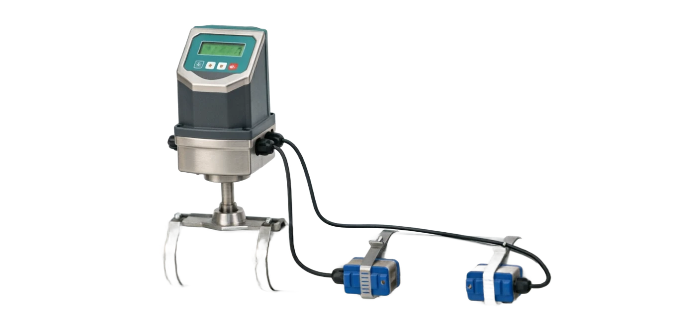
Reference to the ultrasound flow meter classification
Hypersonic Flow Count . Classification reference diagram

Hypersonic flow meter support

Provide survey missions, media and installation conditions and obtain product configuration advice.

Contact us
· Technical Note

TECHNOLOGY & APPLICATION

Understand the principles, the exact selection.

The technical features and selectional elements of ultrasound flow meters are understood from measurement principles to field applications.

01

TECHNICAL GUIDE

Summary of ultrasound flow meter techniques

Measurement principle

Time difference / Dopplerfa Application of mediums: water and multiple liquids Installation: Pyramid external packaging / Inserting / Pipe segment Precision level: ±1.0% ~ ±2.0% Non-contact measurement = Time difference / Dopplerfa Application of clean liquids and impurity-containing liquids

02

MEASUREMENT PRINCIPLE

I. Rationale

The ultrasound flow meter obtains flow speed by measuring variations in the behaviour of ultrasound in the fluid, and then extrapolates the flow. Based on The principles of measurement vary, and are divided into two main categories: Transit-Time and Doppler, where time is spent on the same method. The differential method is the most widely applied type of industry. 1. Time difference method (Transit-Time) Installation of a pair of ultrasound exchangers (one launch, one receiver) on both sides of the outer (or inner) pipe wall The speed of transmission in the direction of fluids varies from that of reverse flows: Δt = tdown − tup = (2 · L · v) / (c2 − v2) ≈ 2·L·v / c2 v = (c2 ⁇ t) / (2 ⁇ L) (c for acoustic speed, L for acoustic degrees) Q = (π · D2 / 4) · v The smooth, reverse-flow time difference ⁇ t is proportional to the flow average v of the fluid, and the ⁇ t is measured to calculate the flow. This method applies to clean. Liquids that are clean, even and free of large bubbles (e.g. water, pure water, chemical solution). Time difference ultrasound flow method Fluid v ( m / s ) A (launch) B (Receiving) Stream Reverse current t_down ⁇ t_down _t_up ⁇ fv 2. Doppler The energy exchanger sends a fixed-frequency f0 ultrasound to the fluid, and reflects back and forth when it encounters a dispersive (particle, bubble) in the fluid Capable, reflect wave frequency f is offset (Doppler frequency shift). fd = f0 · (2·v·cosθ) / c v = (c fd) / (2 f0 coss) (thirty-thirty-mud) Q = (π · D2 / 4) · v Doppler Law requires sufficient dispersors (particle/buff) in the fluid to apply to sewage, sludge, solid particles The slurry. Selective tips: high time difference accuracy ( ± 1%) suitable for clean liquids; doppler method applies impurities-containing liquids but with a slightly lower accuracy (±2%~5%)。 Preference for Dopplerfa in the case of dirty, bubble or particles in the field; Physician clean, impurity-free in the medium, priority The difference.

03

PRODUCT STRUCTURE

II. Structure

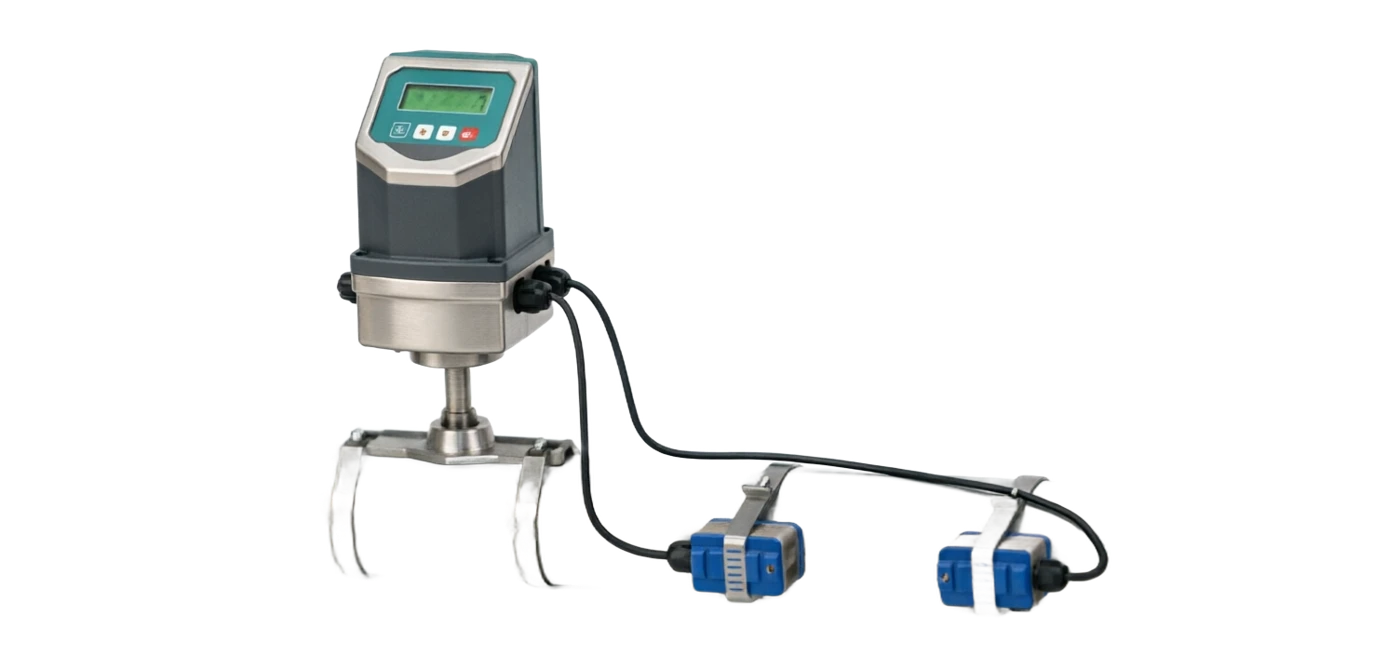
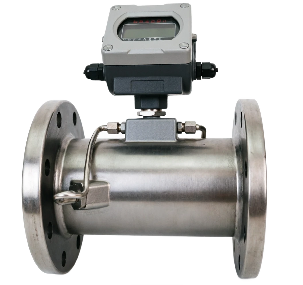
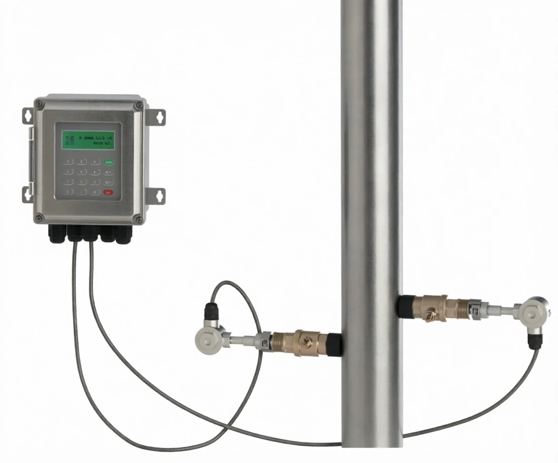
The ultrasound flow meter consists of two components, ultrasound exchangers (probes) and converters (hosts), both of which are wired through a dedicated signal. Cable connection. Depending on the manner of installation, three main categories are defined as outlay, insert, and tube segment. Hypersonic flow meter structure profile (output) Pipewall Fluid V Spectrum (bottom) Power-pressure ceramics W Punctuation (up) Converter CPU . Display Signal processing 4-20mA Special cable Compatible layer Energy Exchange V Power Exchange W Main Widgets Function and description Ultrasound exchanger Core sensor components, made of voltage ceramics (PZT), both for launch and reception; common frequency 1 MHz (central) Small tube ~ 0.5 MHz (large pipe ); divided into three types of installation V/W/Z Converter (host) Generates an incentive pulse, receives signals, calculates time differentials/frequency shifts, displays instantaneous and cumulative flows, provides 4- 20mA / Pulse / Communication Output Fill the air gap between the probe and the tube wall to allow the ultrasound to be efficiently carried into the tube (outlays necessary, commonly used silicon) (Pretty sheeting) Signal cables, two-barrel shield cables, connectors and converters; ≤ 50 m, as usual, as SMS. Installation of a clamp/floor, fixed probes in the external band or magnetic clamp; insertion in the floor of a ball valve with a pulsive opening III. ENOUGH QUESTIONS ♪ Main strengths, main limitations ♪ Non-contact measurements: no stoppage, no breakout Bad pipe, especially for established pipe and corrosive media Mass Non-moveable parts: no pressure loss, no jamming, no Wearing, and we're using the stables. Wide range of application tubes: DN15 ~ DN6000, small It's possible to measure up to the head of the water plume, up to the head of the water plant. Installation easy: external folders can be installed in minutes Load, without prejudice to production Measuring accuracy: Time difference accuracy up to ±1% and no It's influenced by the medium's conductivity, viscosity. Portable inspection: portable aircraft capable of measuring random tubes Specially suited for temporary measurement and leakage screening Two-way measurements: positive and negative recognition for Internet monitors Measure High demand for installation: direct line (formerly ≥ 10D, D) After ≥ 5 D, the location of the probe needs to be accurate Affected by the walls and fluids: tube wall dirt, internal wall decay Erosion, stripping, decaying signals. Bubbles and particle sensitivity: Time difference experienced large-scale bubble loss Effect; Dopplerfa cannot measure when the medium is clean Medium accuracy: sound speed distribution, fraction model Acoustic, usually ±1% ~±2%, lower than electromagnetic/vortex Wheel Large dyslexia signal decay: DN 1000 or more to low Frequent probes, installation and debugging difficulties Higher prices: Same calibre prices are usually higher than electromagnetic currents Measurement

04

APPLICATIONS

IV. APPLICATION AREAS

💧 Municipal water supply Large calibre water distribution supervisor Volume, DMA partition count Volume, minimum flow points at night Parsed 🌊 Sewage treatment In and out, in and out, in and out. Flows, sludge return (more) Doppler Law) 🛢 Petroleum chemicals Oil, oil products, various types Trade in organic solvents and trade in organic solvents Process Metrics ❄ Heating air conditioner Cold and hot water systems, cool water Cycle, energy settlement (changing) (with temperature sensors) ⚡ Electricity industry Fireworks condensate water, cool it. Water, boiler water measurement 🧪 Chemical industry Algebra, corrosive media (Packages to avoid exposure to corruption) - I'm gonna get you a drink. 🚢 Ship ports Ballast water, seawater, fire. Water metering. Portables fit. Ship inspection 🔬 Medicine Purified, injected, cleaned. Clean process pipe (sanitary level) (Request)

05

TECHNICAL SPECIFICATIONS

V. TECHNICAL ARRANGEMENTS

Summary of main technical parameters Parameters Time difference method (Transit-Time) / Doppler Apply pipe path DN15 ~ DN6000 (outside folder DN50 ~ DN6000, insert DN80 ~ DN2000, line mode DN15~DN300) Water and all homogenous liquids (temporal difference) / Pneumonic bubble liquids (Dopulex) Media temperature - 40 ~ 160 °C (up to 250 °C high temperature) Media flow speed 0.01 ~ 25 m/s Precision Level Time difference ±1.0% FS, Dopplerfa ±2.0% ~±5.0% FS Repeatability ±0.2% ~ ±0.5% Plumbs steel, stainless steel, cast iron, copper, PVC, PVC, PE, glass steel, etc. (extra-packet requires sound transfer) Show mode LCD menu in Chinese showing instant flow, cumulative flow, flow speed, signal intensity Signal output 4-20mA, pulse, RS485 (Modbus), HART (optional) Communication protocol Modbus RRU / Modbus TCP, optional GRRS / 4G wireless remote Protection level Converter IP65, Probe IP68 (premised) Power supply AC 220 V or DC 24 V;carrier-in-in-house lithium batteries ≥ 10 h ≤ 15 W (One), ≤ 1 W (Portable) Probe frequency 0.5 MHz (large pipe) / 1 MHz (medium pipe) / 2 MHz (small pipe) Cable Zero 5m, optional 10m / 20m / 30m, maximum 50m Typical flow range for different tubes Common diameter DN time difference flow range (water m3/h) Application of probe type DN15 0.03 ~ 1.0 HF perp 2 MHz, piped DN25 0.1 ~ 4.0 HF perforator, tube segment DN50 0.4 ~16 1 MHz, external folder/ piped DN80 1.0 ~ 40 1 MHz, external folder / insertion DN100 1.5 ~ 65 1 MHz, external folder / insertion DN150 3.5 ~ 150 1 MHz, external folder / insertion DN200 6 ~ 260 1 MHz, external folder / insertion DN300 14 ~ 600 1 MHz, external folder / insertion DN500 40 ~ 1700 0.5 ~ 1 MHz, external folder DN800 100 ~4400 0.5 MHz, external folder / multisound DN1000 160 ~ 7000 0.5 MHz, multi-channel outlet DN1500 350 ~16000 0.5 MHz, multi-channel outlet Note: The above table is based on water (v = 0.3 ~ 10 m/s); other liquids are subject to amendment to density and viscosity. Multi-channel configuration can be significantly enhanced Large routing measurements of accuracy.

06

SELECTION GUIDE

VI. Selected guidance

Five-step selection.

07

SELECTION GUIDE

1 Optimal comparison of measurement methods

Contrast Time difference method (Transit-Time) Doppler Clean, even liquids (water, chemical solutions, oils) containing particles, bubble liquids (supplement, sludge, slurry) Accuracy ±1.0% FS(High) ±2.0% ~±5.0% FS(C) Minimum bubbles require no or very little bubbles. There must be enough dispersors. Typical applications: municipal water supply, heating, cold and hot water, oil, sewage, wastewater, solid phase media Prices higher, slightly lower. 2 installation comparison Means of installation Application of pipe paths Advantages External DN50 ~ DN6000 No stoppage, no breakout of pipe, installation of the fastest signal affected by the tube wall, slightly lower accuracy of large lumber Inserted DN80 ~ DN2000 high accuracy, pressurized installation, value for value opening, stop or pressurized opening Plumb DN15 ~ DN300 highest accuracy, strong signal, identifiable need to cut pipe, install complex, highest price Portable DN20 ~ DN6000 hand-held inspection, temporary measurement, non-prevalence fixed measurement 3 Punctuation V/W/Z Clear media Clean, smooth, time differential. Contains particles/buffs Dopplerfa. 1 Confirm the pipe path. DN15~DN3000 The main track is multisound. 2 Select Installation Outlet / Insert / Sector Select by Needs 3 Determine Precision Trade settlement ±1% Process monitoring ±2% 4 Output and Communications 4-20mA / RS485 Modbus / HART 5 how? The two probes are mounted on the same side of the tube, and down, with the strongest signal for the small DN50 ~ DN300 medium tube. Z method Two probes on both sides of the tube, DN300 ~ DN1000 large tube diameter to avoid signal failure Less W Law Two probes on the same side of the tube (similar to V but mixed) Different) DN100 ~ DN500 medium diameter Louder! Dow Multi-to-penetrating probes distributed around circles (2 / 4 / 8 channel) DN1000 and above large tube diameter, trade settlement, high Precision

08

SELECTION GUIDE

4 Media and flow-spectrometry

Media type Recommended method Recommended installation Typical flow speed (m/s) Water for running, life hot, time difference externals / section 1.0 ~ 3.0 Sewage, Wastewater Dopplerfa Pocket 0.5 ~ 3.0 Chemical acid alkaline time difference external trap (corrosive probe) 1.0 ~ 3.0 Oil, finished oil Time difference method, piping / insert 1.0 ~ 5.0 Water, fire water Time difference external folder / Insert 1.5 ~ 4.0 Cold-circle water Time difference / outer packaging 1.0 ~ 3.0 Mud, pulp, Dopplerfa, externals 0.5 ~ 3.0 Vapour condensed water Time difference, pipe segment 0.5 ~ 2.0

09

SELECTION GUIDE

5 Output and Communication Selection

Demand scenes. Recommended configuration. Access DCS / PLC simulation capture 4-20mA simulation output Trade settlement, flow calculator support, pulse output + RS485 SCADA Remote Monitor RS485 (Modbus RRU) Remote unmanned station 4G/GRRS Wireless Remote Passage + Modbus HART protocol with flow computer/ energy gauge Demand scenes. Recommended configuration. Data Cloud Platform Accessed Modbus TCP / MQTT / 4G DTU Selective prompt: 1 prioritizes the clarity of the medium cleanliness (decision time difference vs doppler method); 2 large tube path ⁇ DN800 strongly recommends Multi-channel configuration; 3 Trade measurement scenarios must be piped + field marked; 4 Pre-installation confirmation of straight-line segment zidness (upstream) ≥ 10D, downstream ≥ 5D) meets the requirements. ⁇ Summary of 2026 Flow Calculator Technology · Ultrasonic Flowmeter = Chapter 6