PRODUCT TECHNOLOGY

Magnetic Float Lamp Count

Operating principle

Magnetic floats liquids.

A floating ball is embedded in a ring or column of permagnetics (usually cylindrium N35-N52), which produces a strong magnetic field evenly along the float round. When the ball moves up and down the catheter through the outer cavity of the Reed Switch, the magnetic field acts to bind the metal springs in the clarinet and to produce a closed (or disconnected) switch signal. The springs after the ball leaves return to their condition with their own ballistic force, forming a passive, reliable magnetic switch contact. The installation of multiple dry clarinets (typical 2, 3, 4) at different heights outside the catheters allows the output of multiple warning signals, such as "low liquid" , "low liquid" , "high liquid" , "high liquid" , etc., respectively. The spacing between switches is the liquid-level action value, which allows for different warning/ control thresholds by adjusting the position of the clarinet at production

  1. 01

    (b) Floating on a float when F > G;

  2. 02

    (b) When F < G , the floater sinks to the bottom of the cavity;

  3. 03

    F = G at balance, the float stays at the balance position of the liquid surface.

  4. 04

    The resulting wave of reversals is detected by wave catheters measuring accuracy up to mm. In addition, magnetic reed-based resistance remote transmission is used through a magnetic reed switch that is evenly distributed.

Magnetic Float Liquid Rating Support

Provide survey missions, media and installation conditions and obtain product configuration advice.

Contact us
Magnetic float fluids . Technical description

TECHNOLOGY & APPLICATION

Understand the principles, the exact selection.

From measurement principles to field applications, the technical characteristics and selection features of the magnetic float gauge are understood.

01

TECHNICAL GUIDE

Overview

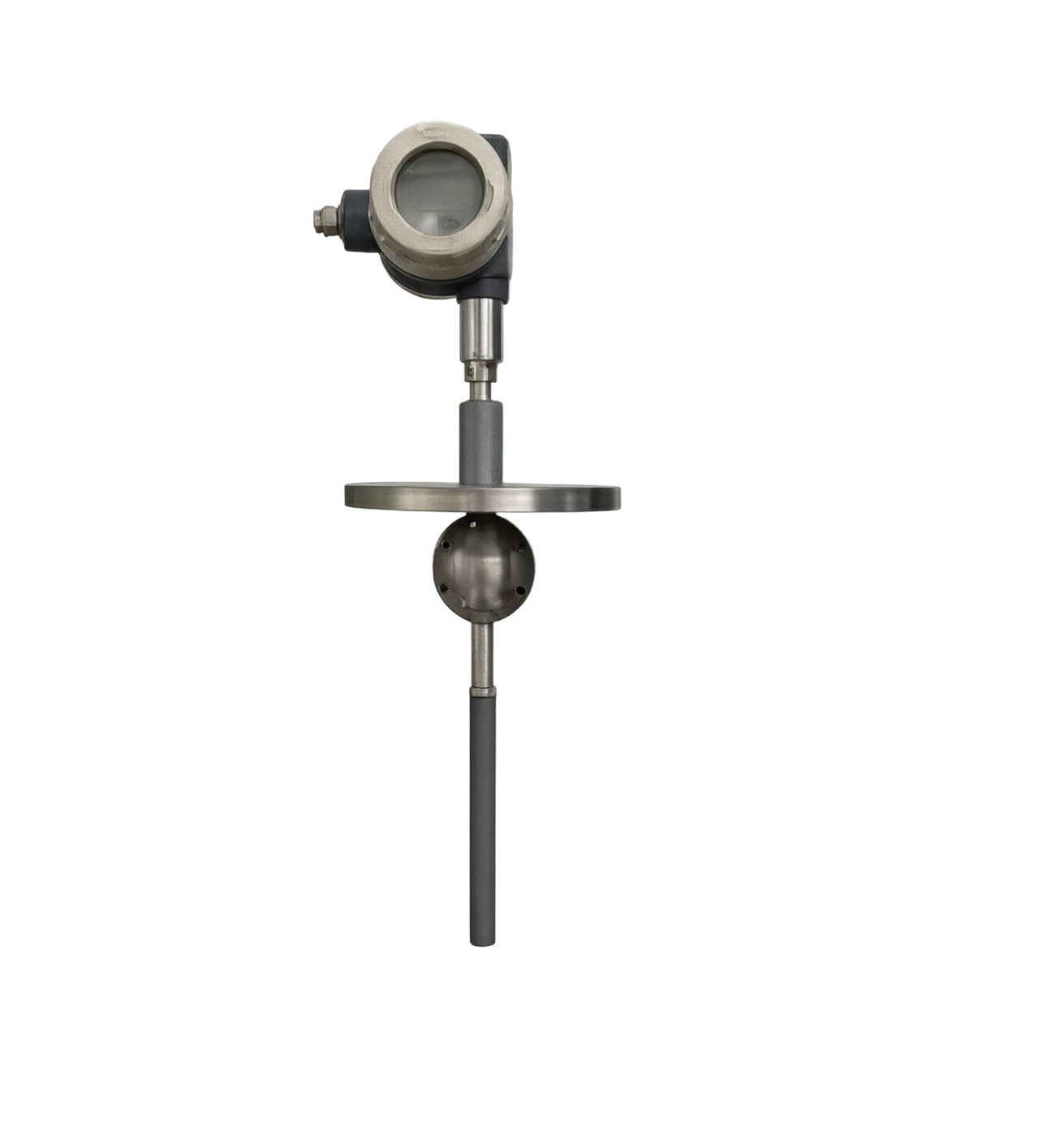
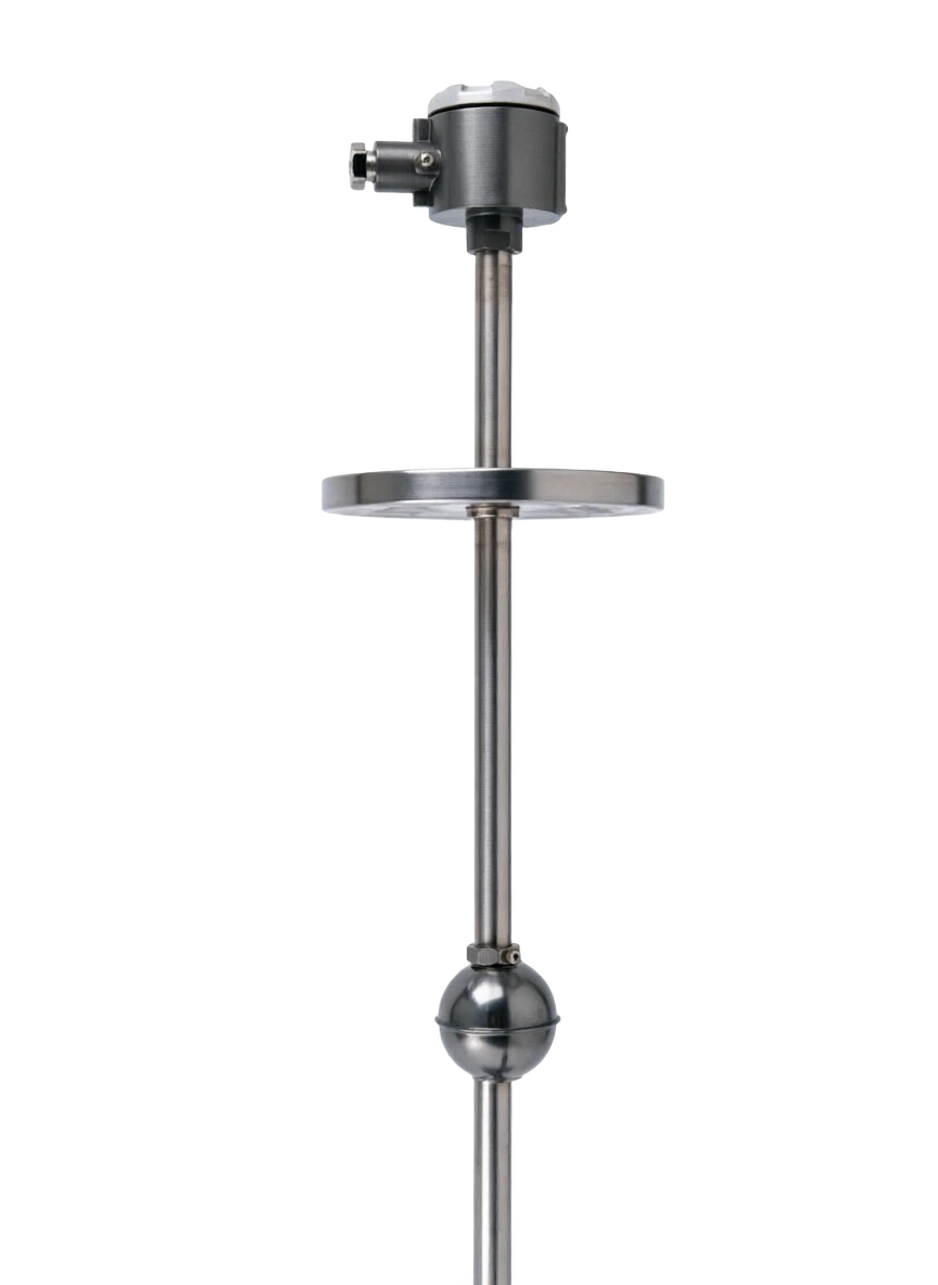
(Magnetic Float Level Switch / Transmitter, commonly known as Float Point Switch, Magnetic Float Platometer) LSD is based on the Akimid Float Law and Magnetic Compatibility Principles. Float (inline permanent magnets) drops with liquid position, and the magnetic switch (dry spring) is activated by magnetic coupling to trigger the signal of the switch outside the cavity, or by the remote transmissor output of the continuous signal of 4-20 MA.

The high- LLEU alert, automatic extraction pump control and liquid-lock protection, especially for equipment such as industrial storage tanks, reaction plumes, water tanks and pools, are among the basic liquid elements with high value in process control. It can be used both separately for the achievement point spot testing and as a multi-stage switch for the segment monitoring of liquids.

This document will provide a systematic elaboration of the rationale, structure composition, comparison of strengths and weaknesses, application areas, technical parameters and selection guides, which will provide a reference for engineering design, equipment selection and on-site maintenance.

02

MEASUREMENT PRINCIPLE

Operating principle

2.1 The rationale for floating balance

Linking to the detectable container by flanges or threads, forming a connector structure.

G-G and F-F combined effects

b

  1. 01

    (b) Floating on a float when F > G;

  2. 02

    (b) When F < G , the floater sinks to the bottom of the cavity;

  3. 03

    F = G at balance, the float stays at the balance position of the liquid surface.

As the fluid surface of the medium is consistent with the liquid surface of the cavity, the float position can indicate the real-time liquid level in the container.

2.2 Magnetic coupling and switch triggers

A floating ball is embedded in a ring or column of permagnetics (usually cylindrium N35-N52), which produces a strong magnetic field evenly along the float round. When the ball moves up and down the catheter through the outer cavity of the Reed Switch, the magnetic field acts to bind the metal springs in the clarinet and to produce a closed (or disconnected) switch signal. The springs after the ball leaves return to their condition with their own ballistic force, forming a passive, reliable magnetic switch contact.

2.3 Multi-level liquid level testing

The installation of multiple dry clarinets (typical 2, 3, 4) at different heights outside the catheters allows the output of multiple warning signals, such as "low liquid" , "low liquid" , "high liquid" , "high liquid" , etc., respectively. The spacing between switches is the liquid-level action value, which allows for different warning/control thresholds by adjusting the position of the clarinet during production.

2.4 Continuous liquid position measurements (distant)

If a continuous 4-20 MA liquid level signal is to be obtained, magnetic scalable remote transporter can be installed outside the cavity: page 3 of the Float magnet moves into a precise electrical resistance circuit, approximately ± 5 mm accurate.

2.5 Signal transmission path

Page 4

  1. 01

    The resulting wave of reversals is detected by wave catheters measuring accuracy up to mm. In addition, magnetic reed-based resistance remote transmission is used through a magnetic reed switch that is evenly distributed.

  2. 02

    ±1 +

Motion of work . Serial number / chainCross-reference
Serial numberLinkFunctional description
1Tested packagingsProvides raw liquid-level signals
2Up/ Down Takeover / FrankConnected cavity and packagings
3A cavity or catheter internal mediumConnect to container internal medium
4FloatFeel the surface position (floating balance)
5Floating SteelGenerate a strong magnetic field.
6Spring tube switch.Magnetic coupling, output switch.
7Operator Box / PLC / DCSReceive alarms / Control signals
8Remote Transmitrator (optional)Output 4-20 MA + HART
03

PRODUCT STRUCTURE

Product structure

3.1 Typical structural composition

Composed of five major components of the catheter (clause), float, magnetic switch components, wired boxes and process, with points

The three categories are "Switch" and "Experipher" and "Switch+Existing Complex".

3.2 Typical structural diagram (text description)

Top plug / exhaust valve ( 8 ) / cavity () 1 ) Float ( ) 2 ) (Code internal, cavity with magnets) Dry clarinet switch (Cyber core) 3 ) (The outside of the catheter, 1 ~ 4 ) Remote Transmitters (Pyrotransmitters) 5 ) & & & Connect Box (optional) 6 ) Bottom support / sewage valve ( 9 ) ⁇ Process Connection ( 7 ) ⁇ Tested packagings.

3.3 Structure Classification

Page 5, page 6

Aluminum/ cavity (supervisor)

Main function: Connect to containers, provide moving space up and down in floats3 Usual materials / Specifications: 16L / 304 / Hax/ titanium / PP / PTF

Float (float)

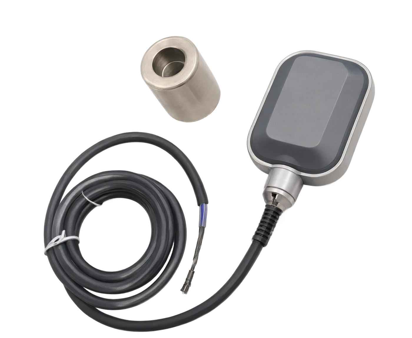
Main function: Feel liquid surface position (floating balance), 3 x 16 permanent L magnetic/Hatz, common mass/ specification: G/ titanium / PP / PTFE (inline N35-N)

Magnetic switches (dry-clarine tubes)

Main function: Detection of float position, output alert / control signal constant Usage / Specification: open / constant closed / SPDT switch, dry clarinet contact

Switch Location Adjustment

Main function: Repositioning of the dry clarinet above and below the catheter Common material / specification: adjustable cardring / slider / fixed bolt

Remote Transmitrator (optional)

Main function: Converting liquid position to 4-20 MA + HART signal Usual material / Specification: Magnetic stretching / magnetic reed electrical resistance

Switchbox / Connector End

Main function: Electrical interface and seal Usage / Specification: Aluminium alloy / stainless steel / IP65/IP67

Process connection

Main function: Linking to container take-over French or screwdriver D Usual material / Specification: N25 / NN50 Frank / 1/2 NPT / G1

Top Block / Eros Valve

Main function: Sealed cavity, disabling internal gas, common mass / specification: 316L + PTFE seal

Bottom support / Erosion valve

Main function: Supporting the lower limit of the float, sewage cleaning, commonly used materials / specification: 316L + ball valve

Shields (optional)

Main function: Prevent the out-of-the-front influence of the clarinet and the connection Usual material / Specification: Transparency PVC / Metal shield

Press output signal

Type: Pure switch type characterization: clarinet output switch only, no remote transmission

Type: Switch + Remotely transferred complex

Type: Pure apogee description: output only 4-20 MA, no switch

By installation

Type: Side-loading Description: Connecting to the side wall of the container through a flannel or screw

Type: Top-loading feature description: Floating ball inserted from top of the container

Type: external (bracket) characterization: magnetic floats mounted on the outer wall of the container (triggered outside the magnetic ply)

Press switch levels

Type: Single point switch characterization: 1 road alarm / control

Type: Two points switch characterization: 2 routes, e.g. low liquid + high liquid plaque

Type: 3 o'clock / 4 o'clock switch Feature: 3 ~ 4 LSD alert

Open (NO): Closed (NC) Touch closed when the float is in place: the touch is disconnected when the float is in place

Open (NO): Switch (SPDT) touchpoint closed when the float is in place: public + open + closed three lines

04

TECHNICAL GUIDE

Analysis of strengths and weaknesses

4.1 Main advantages

It's simple and compact.

Specific: Pipe + Float + Dry-crest structure, small, light, easy to install.

High reliability

Specific: Direct contact media without mechanical motion parts, with dry clarinets having a life of more than 10⁸, and MTBF high.

- No-source switch signal. - Fuck.

Specific: larin contact point can output switch volumes without electricity to facilitate access to PLC / DCS / relay circuits

- Multiple liquid level tests. - Yeah.

Specific: Output 1~4 at the same time of alarm/ control signal, achieving "low/ low/ high/ high" multi-calibration lock

The medium is adaptable.

Specific: By replacing floats and catheter materials, they can be applied to a variety of media, including water, oil, acid, solvents, etc.

Price economy

Specific: Machine prices are much lower than magnetic stretchers/complex liquid-level transmitters such as radar, which are the preferred option for base control

Flexible installation

Specific: Various modes of side-dressing, top-covering, externaling, suitable for various types of field conditions.

Respond Quick

Specific: Float is activated immediately when moving to the dry spring position, and response time is usually & lt; 50 ms.

Maintenance waiver

Specific: No mechanical seals worn, no electronic components exposed to the medium, with long useful life.

Disadvantages and use restrictions

Measuring limited accuracy Pure Switches

Response response proposal: Type only identifies discrete liquid levels, with a long-range accuracy of approximately ±1 ~5 mm, lower than magnetic scalability ±0.5

Not applicable to sticky, crystal-friendly media

Response recommendation: Floats may be packaged, carded or clogged, resulting in a failure to trigger the switch properly.

Not applicable to solid particles mediums containing large quantities

Response response proposal: particulate matter easily clogged between the flounder and the cavity, causing a card delay.

Poor medium density adaptation

Response response proposal: Condensity medium needs to replace floats of different weights, which deviate from the balance point when density changes are greater

Switch position adjustment to restricted clarinet

Response response proposal: Once the location of the installation is determined, the switchbox will be re-established if adjustments are needed, resulting in on-site maintenance

Vertically Installed

Response measures recommend that the tube must be vertically secured, otherwise the float is blocked or the switch position is less accurate.

Installation space requirements

Response response measures recommend that side-loading should take up the outer wall of the container and top-filled space.

Touchage limit dry clarinet contact

Proposal for response measures: a point capacity rule ≤ 60 W / 230 V AC, not directly driving large power load, needing relay power

Magnetic interference is sensitive, strong.

Response response proposal: The magnetic field environment (e.g., by large electric power) may be wrongly triggered by the drying tube, with a reasonable layout or magnetic shielding

05

APPLICATIONS

Application area

Extensive use in the following industries and scenarios:

Page 7, page 8

Water treatment and municipalities

Typical application scenarios: water tanks, fire-fighting tanks, sewage tanks, water-clearing pools, water-gathering pits, water purification equipment liquid level alerts and pump control

Building and heating

Typical application scenarios: AC expansion tanks, boiler recharge tanks, FREE expansion tank monitoring of fluid levels.

Petroleum chemicals

Typical application scenarios: small storage tanks, buffer tanks, response high LSD alerts, oil water separator interface monitoring.

Gas and gas storage

Gas stations bury tanks, light oil tanks, washing tanks, water points.

Electricity

Condensate water tanks, high-pressure heaters, salt water tank fluid level control.

Pharmaceutical industry

Sterilization tanks, feedstock tanks, CIP Re-water tank liquid level monitoring (sanitary level optional).

Food and drink

The sugar can, the juice can, the milk can fluids are reported.

Metal and metal

The acid wash, electroplating, emulsion tank fluids are reported to be in the water.

Paper industry

Monitoring of liquid levels in slurry ponds, white water towers, black liquid tanks.

Chemical light work

(c) glucose, dye, catalyst-slurry tanks (when heated) etc.

06

TECHNICAL SPECIFICATIONS

Technical Parameter Table

The following parameters are generic technical indicators of typical magnetic float-levels, and the actual product parameters are based on the manufacturer's exit data table.

Page 9

Technical parameter table · Parameter item / Specification parameterCross-reference
Parameters itemSpecification parametersRemarks
Measuring span100 ~ 6000 mm (Cash type)Teleports up to 12,000 mm
Measuring precision (switch type)±3 ~ ±10 mmDepending on the precision of the drying tube position.
Measurement precision (distant)± 1 mm (magnetic scalding) ± 5 mm (magnetized reed electrical resistance)It's different from the teleport program.
Medium density≥ 0.45 g/ cm³ (Standard Float)Customised ≥ 0.35 g/ cm³ low density type
Operating pressure0-1.0 MPa (General)/ 0-2.5 MPa/ 0-4.0 MPaHigher stress will have to be customised.
Process medium temperature40 ~ +150 °C (conventional) high+200 °C/ Special to reach +450
Ambient temperature40 ~ +70 ℃The clarinet is less affected by the low temperature.
Environmental humidity5% ~ 95% RHNo condensation
Ingress protectionIP54 / IP65 / IP67IP65 and above
Explosion protection markingExia ⅡC T6 Ga / Exd ⅡC T6 GbBased on GB/T 3836
Process connectionPN25 / DN50 Frank (HG/T / ANSI / DIN)Custom screw, sanitary grade Tri-Clamp
Switch point capacity≤ 60 W / 230 V AC (standard)High power size up to 100 W.
Touch formOpen NO / Closed NC / Convert SPDTBased on field control logic
Switch response time≤ 50 msFloat in place.
Switch life≥ 10⁸ times (unloaded)Full Load Life ≥ 10 ⁵ ~ 10 Number of times
Switch levelsLevel 1 / 2 / 3 / 4 (General)Specially designed to reach level 5 or higher
Main material 316L/ 304 / Haps Alloy C / titanium / PP / PVC / PTFE lineIt's based on the medium's corrosivity.
Float material316L / Harsh / titanium / PTFE / PPBe compatible with media
Accompanying mode (optional)Vapour clamp / electric companion tropicalConfigure media when crystallized
Remote Transfer Out4-20 MA + HART (optional)Magnetic Zoom / Magnetic Reed Resist
Response time (apogee)≤ 0.5 sIf the medium is highly volatile, it can be stopped.
Communications agreementsHART 7 (required only for remote transfer)Switches do not require communication
AuthenticationCE / ATEX / IECEx / NEPSI / CCCMeasurement CMC Authentication Optional
07

SELECTION GUIDE

Select Table

This section provides an option reference for five dimensions of "quantitative specification", "work pressure", "work temperature", "appliance scenario", "process connection" and allows engineers to quickly locate the model.

7.1 Table of selected types by Quantities and Switches Levels

7.2 Table of Type by Work Pressure

7.3 Table of type by working temperature

7.4 Table of types by application

Page 10

7.5 Process Connection Form Spacing

Page 11

Selective table · The quantum code / range of the rangeCross-reference
The quantum code.Measuring spanRecommended number of switch levelsTypical applications
RC-01100 ~ 500 mmLevel 1Small buffer tanks, water tanks
RC-02500 ~ 1500 mmLevel 2General tanks, pump pits
RC-031500 ~ 3000 mmLevel 2 ~ 3Medium Response
RC-043000 ~ 6000 mmLevel 3-4Large storage tanks
RC-056000 ~ 12000 mmLevel 4 + ApogeeLarge canisters, towers
Pressure codeOperating pressureTypical applications
PC-A0–1.0 MPa (average pressure)Water tanks, tanks, fire tanks
PC-B0–2.5 MPaGeneral pressure vessel, reaction sheet
PC-C0–4.0 MPaPressure container
PC-D≥ 4 MPaCustomized, special structural design required
Temperature CodeProcess medium temperatureTypical applications
TC-N40 ~ +80 ℃Temperature water, oil tanks
TC-M40 ~ +150 ℃Hot oil, medium temperature medium
TC-H40 ~ +200 ℃High temperature heat medium
TC-U+200 °C and aboveCustomized, high temperature bearing structure
TC-L196 ~ -30 ℃LNG, LSD, deep cold medium
ApplicationsMedia FeaturesSuggested selection elements
High-Low Watershed Fire PoolTemperature Water, IP65RC-02 + 2 Level Switch + IP65 + 316L
Sewage pump controlParticle sewage, corrosivePP / PVC + RC-01 + external poster installation
Boiler water tankTemperature, saline water316L + RC-02 +3 Level Switch + HLID Level Alert
Select Table . Reacting Pu-Liquity / Corrosive / High TemperatureCross-reference
Reacting Pu-Liquor-LockingCorrosive / High TemperatureHSD / titanium + RC-03 + TC-M + SPDT
Low-Lavigen Protection in Condensed Water TanksCold water.TC-N + RC-01 + Closed NC Contact + Low L.D. spot stop pump
Gas station cans.Petrol / dieselExia blast protection + 316L + 2 Level Switch + Cable fluid table switch
Hydraulic tank low-liquid alert.constant temperature hydraulic fluid316L + 1 Level Switch + NC Contact
LNG / LSD tankDeep cold - 196 °CTC-L+OZ +Special cryogenic seal
Health-grade storage tanksCIP/ SIP request316L polish + Tri-Clamp + Health Level Certification
Sticky / Flex-Cordable MediumHigh viscosity / crystallityCompassed heat (steal) + TC-M + Large caliber French
Connection codeFormSuitable operating conditions
C-F25DN25 Frank (Standard for Side Load)General tanks, buffer tanks
C-F50DN50 FlangeTop, large canisters.
C-N121/2 NPT inner screwSmall equipment, low pressure
C-G12G1/2 Inner screwEUROPE, MINORIARY EQUIPMENT
C-Tri50DN50 Tri-ClampHealth level, food / medicine
C-EXTExternal poster (tips)Unopenable pipe / outer wall of container
08

SELECTION GUIDE

Selection of guidance and attention

8.1 Selective Steps

8.2 Installation and use of attention

  1. 01

    The instrument verticality (recommended deviation ≤ 1 %) must be guaranteed, otherwise the float ball may be stuck.

  2. 02

    The distance of the upper/lower takeover of the French centre must be strictly consistent with the distance of the two French centres.

  3. 03

    The flange's tight bolts should be cross-cut, symmetrical and evenly increased to avoid single-sided receptors.

  4. 04

    The impurities and transport fillings in the cavity shall be cleaned and, if necessary, water test operations shall be performed to verify the smooth rise and fall of the float.

  5. 05

    The location of the clarinet should be set to lock the regulator to prevent the vibration from causing the location to drift.

  6. 06

    The outdoors should be equipped with rain masks to avoid damping of the clarinet / connection.

  7. 07

    Relays should be expanded to avoid overloading of the clarinet contact point when the capacity of the contact point is greater.

  8. 08

    Long-range signal transmissions should be made using shield cables, with a single end of the shield layer.

  9. 09

    The installation of hazardous sites must meet the requirements of the blast-proof level for the wiring and location.

  10. 10

    (c) A distance from the sources of interference in the field of powerful magnetic fields such as large electric generators, transformers and, if necessary, magnetic shielding.

  11. 11

    The inner cavity is to be cleaned and closed and the French interface sealed.

8.3 Maintenance and troubleshooting

Page 12 -- End of document --

Selected guidance and attention . Steps / Key elementsCross-reference
StepsKey elements
Step 1 . Clear measurement missionConfirms whether to call the + control of the single point alarm/ multiple alerts/ continuous measurements.
Step 2 . Confirm media parametersMedia name, density, viscosity, temperature, pressure, corrosivity, particle content.
Step 3 . Confirming the scaleSelect the side load / top load and quantification specifications based on the geometric dimensions of the packaging and the desired liquid-level action points.
Step 4 . Select the number of switchesSelect the 1-4 level switches based on the control needs, and make a preliminary estimate of the location of the switch actions.
Step 5 . Select the contact formSelect NO/ NC/SPDT according to the field control logic.
Step 6 . Selecting materialSelect the liner 316L/Hastium/PP/PVC/PTFE based on the corrosive properties of the medium.
Step 7 Confirm blast and protectionThe blast-proofing level and the protection level are selected according to the hazard area on site.
Step 8 . Select Process ConnectionSelect the French/ screw/ sanitary Tri-Clamp/ external sticker based on the container interface.
Step 9 . Supportive relays amplificationIf the load is large, it needs to be accompanied by intermediate or solid-state relays.
Selection guidelines and attention · Common failures / Possible causesCross-reference
Common malfunctionsPossible causeSuggested measures
Float up and down.Crushing / crystal / particle accumulationDismantling cavity clean-up, with heating if necessary
The clarinet doesn't trigger.Float magnets fail / dry clarinet damage / wire openChange float/ clarinet, check the circuits.
Error TriggerDrain position drift / Strong magnetic field interferenceRelock position, magnetic shield.
Selector Guide and Attention . Touchburn / Touch overload / Sensible Load Unexploded ArcCross-reference
Touches burned.Touch overload / Sensory load unexploded arcReplacement of clarinets, plus RC arc elimination / relay extension
Media leakFranc seal is dead / Float is brokenReplace seals / Float, tight Frank
The teleports are off the grid.Remote Transmitrator failure / Connection openCheck for telepower, check for circuits, replace transducers
The touch is not very sensitive.Old clarinet / Floating Steel RetardChange clarinet / Float