
PRODUCT TECHNOLOGY
Smart Separator
Operating principle
- Smart separators. - The working principles.
General structure: The signal moving smart separator on the barrier consists of four parts of "Input reconciliation + separation coupling + output drive + smart human interface". The input signal is first regulated by the electrical circuit: the active current is converted from sample to voltage, the passive current signal is detected after the internal electricity is supplied by the isolation device, the voltage signal is taken directly by subpressure, thermal doll/thermal resistance signal is specially regulated (including cold end compensation and incentive currents). The adjusted signal is transmitted through the insulation level (e.g. electromagnetic or linear photo-separation of transformers) across the insulation barrier to the output side, and then the output is targeted by the V/I or V/V conversion. The entire signal chain is only connected by magnetic or photocolumn between the input side and the output side, with no public electrical nodes, and insulation is typical of 1500~2500V -- this.
- 01
• 4 - 20 mA signal flow for external power supply has been converted from internal sample resistance (typical 50 ~ 100 times) to voltage detection; separator does not provide power to input circuits • Input pressure reduction 0.5 ~ 2 V; precision 0.1% ~0.2% FS
- 02
• Separators feed suspended power source two-line signals via isolation to input circuits (transverse power of the transmitter is used on occasion by the relative equipment) · Equivalent load 250 times; feedback voltage 20~28 V
- 03
Power input . 0 - 10 V / 1 - 5 V / 0 - 5 V signals enter a level of isolation after high-deductive fractional pressure and buffer, typical resistance not less than 100 k . Precision 0.1% ~0.2% FS
- 04
Temperature input (partial machine type) Thermal electromechanical dolls are adjusted by cold-compensation, heat resistance is tested by a three-/ four-line system with constant current incentive, converted to standard mA/V output . CJC 0.5 degrees Celsius; Pt100/Cu50, etc.
Structure
- Structure.
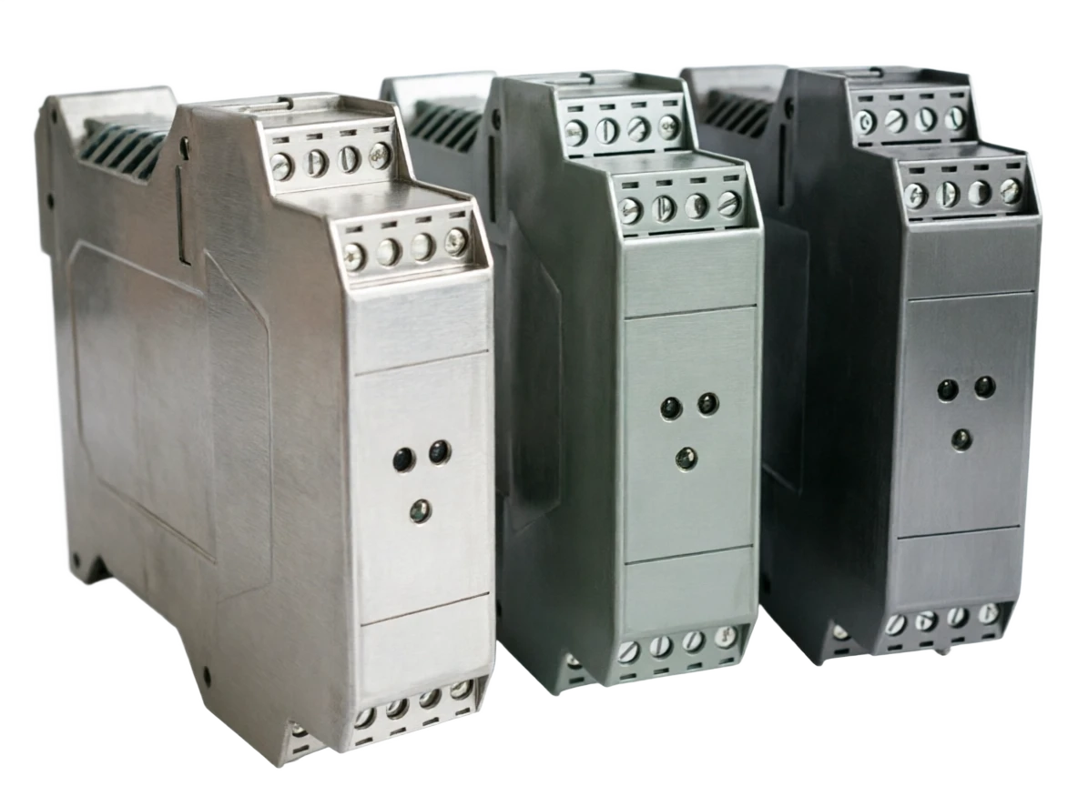
The whole-form smart separators are equipped with thin casings using the DIN 35 mm track, typical of the single-channel width of 6.2 ~ 12.5 mm (the passive simple type can reach the 6 mm level), and the two-out/two-channel machine mm, the most compact type of interface equipment in the family. (a) The frontal placement of digital display windows, group keys and LED status lamps; Enter/output/power endpoint partitioning, without blue marking, because there is no blast-proof endpoint. Supporting the installation of power supply in the back of the remittance line alongside ultra-high density. Table 3 - 1 One of the trends in the structure of the ISP is extreme thinning: passive simple pressure on 6 mm-scale width, with further compression of the 100-channel cabinets; Second is input altruization: a shell toggle mA/V/TC/RTD input formula
- 01
5-20mm, depth about 100-124.
- 02
Table of advantages and disadvantages 4-1 Table of main advantages 4-2 Table of main weaknesses and responses
- 03
• Fire retardant project plastics (UL94 V-0), DIN rail card button, width 6.2-20 mm (photo-functional) • Most compact in the family; high-density cabinets preferred; endside no blast-proof spacing limit
- 04
Show cell . 4~5 bit LED digital tube displays project volume or current/voltage value, key switching displays input and road output level . 0.2; power reduction can be closed
Application area
Intelligent separator • Application field
Table 5-1 Typical application areas and scene pattern 5-2 Six typical application models for smart separator, by functional configuration and target market, divide the common machine types into four tranches. The specifications are based on the latest manufacturer sample. The device is the right answer. Then you lock the specific model by the four elements of "Input Properties + Output Properties + Precision + Smart Functions". Table 8-1: Summary of selected decision elements, typical scenario for decision path one: Four-line transmission to the Fire Power Plant (FPP) access DCS. Transponder powers independently, output active 4-20mA, on site, and control room system, with a drifting signal - should select "source maA input" + two active maA output + numerically visible machine type, to be sent to DCS, to plant level
- 01
Technical parameter table (typical machine type)
- 02
The selection guide for the decision-making factor smart separator follows the common family question: Is the circuit implosion-resistant? Is the live instrument a feed? - If both questions are not, the device is isolated.
- 03
Scenario III: Water plant online analyser signals are multiple-headed. COD MA, which is required to deliver both operating systems, environmental digital devices and third-party monitoring platforms - Select "sourced input"
- 04
Analyzer output is active +
Selection Guide
- A guide to selection.
The complete description shows the technical sections.
Model Selection SELECT A MODEL
1 Model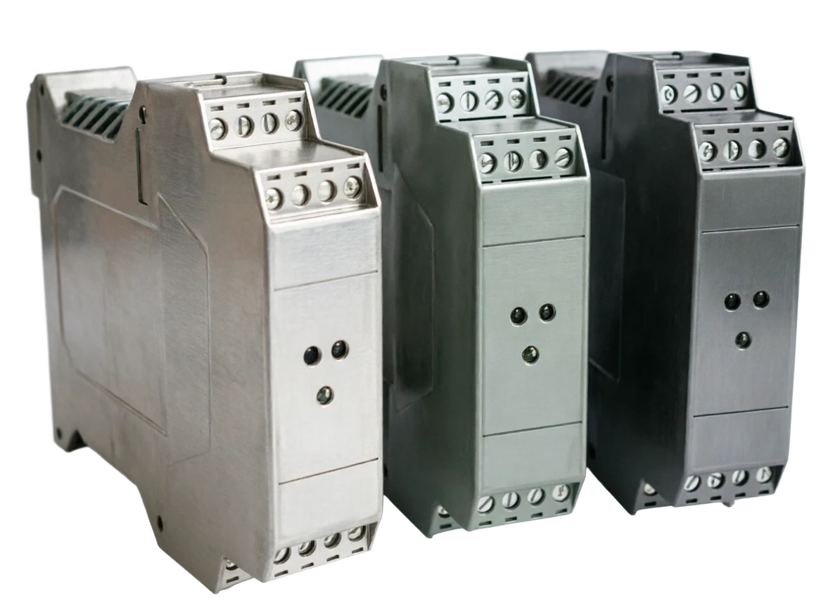
Smart Separator Selection Support
Provide survey missions, media and installation conditions and obtain product configuration advice.
Contact us