PRODUCT TECHNOLOGY

Porosity Flowometer

Operating principle

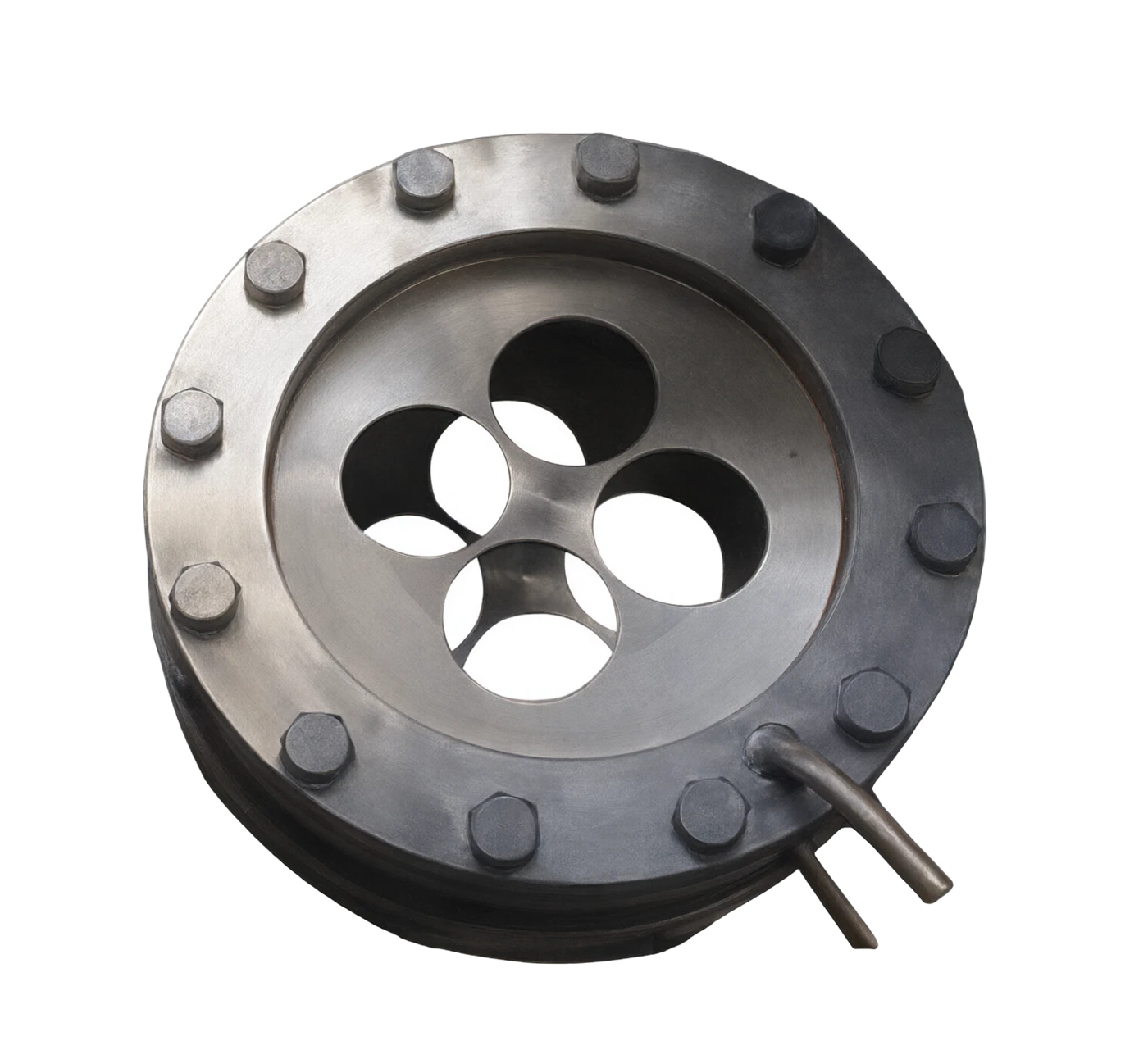
Pyramid flow meters.

and work: when a fluid is installed through a thin sheet with a central convection (poreboard), the fluid beam is compressed at the hole, the flow speed is raised, the pressure is reduced, and the pressure is spread down and above the hole plate. The square root of the pressure is proportional to the volume flow. Flow formula Q = C E ε (πd²/4) ⁇ (2 ⁇ P/Old) Type m: C for the flow factor, E for the progressive speed factor, E for the inflation factor (gas), d for the perforation aperture, and P for the core characteristics of the "discharge pressure ⁇ flow" is the differential relationship pressure, the constant medium density. The only flow porescales that can determine the flow factor "calculated by standard, without actual flow marking" are the levels of standardization. Just press GB/T 2624 ()
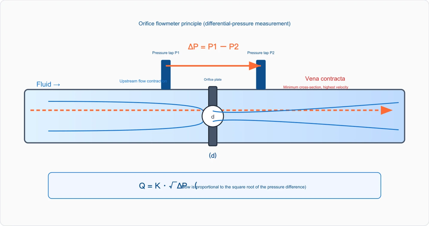
Pyramid flow gauge (discretionary throttle)
ΔP = P1 − P2
P1 Sequester P2
Upstream (constriction) Perforate (Vena Contracta)
Fluid
The smallest cross-section, the fastest flow.
d
(d)
Q = K. ⁇ P. (Flow-to-pressure square root)
A schematic of the principles of work

Pyramid flow meter selection support

Provide survey missions, media and installation conditions and obtain product configuration advice.

Contact us
Pyrometric flow meters Technical note

TECHNOLOGY & APPLICATION

Understand the principles, the exact selection.

From measurement principles to field applications, the technical characteristics and selection elements of the porosity flow meter are understood.

01

MEASUREMENT PRINCIPLE

Operating principle

(energy constant)

And work.

When a thin sheet with a central convection (pore plate) is installed through the fluids, the beam is compulsorily constricted, the flow speed rises, the static pressure falls at the hole, and the pressure spreads up and down the plate. The square root of the pressure is proportional to the volume flow.

Flow formula Q = C E ε (πd²/4) √(2·ΔP/ρ)

Measurement formulaClick to see the big picture
Q = C · E · ε · (π d2 / 4 ) · √( 2 ·P/Old) Q = K = P (as a combined flow factor, determined by the geometry of the pyrotechnical plate) Mass flow: q = K = (Old ⁇ P) m

In m

C The core characteristics of the flow factor, E for progressive speed factor, d for permutation factor (gas), d for permafrost aperture, and P for "discharge flow" are the differential relationship between square root and constant medium density.

, that is, the flow increases 1 times, the pressure differential increases 4 times.

Technical IconClick to see the big picture
Pyramid flow gauge (discretionary throttle)
ΔP = P1 − P2
P1 Sequester P2
Upstream (constriction) Perforate (Vena Contracta)
Fluid
The smallest cross-section, the fastest flow.
d
(d)
Q = K. ⁇ P. (Flow-to-pressure square root)

The only flow-line porosity system that can be used to determine the flow factor "calculated by standard and not by actual flow" is the flow-line porosity meter. The exit factor C for the construction and installation of GB/T 2624 (equivalent to ISO 5167) can be calculated by formula, without the need to mark it by desk - one of the greatest technological advantages of the plume.

Critical understanding

The FPR is measured by '". The ⁇ P is measured by the FPR, and the square is multiplied by the flow factor to crush the mass scale ratio (square root characteristic)

To flow. So it's naturally carrying, inherent limitations.

  1. 01

    The differential pressure (scaling) flow meter.

  2. 02

    The most classic, most widely applied of the Bernouli equation. It is based on the

02

PRODUCT STRUCTURE

Structure

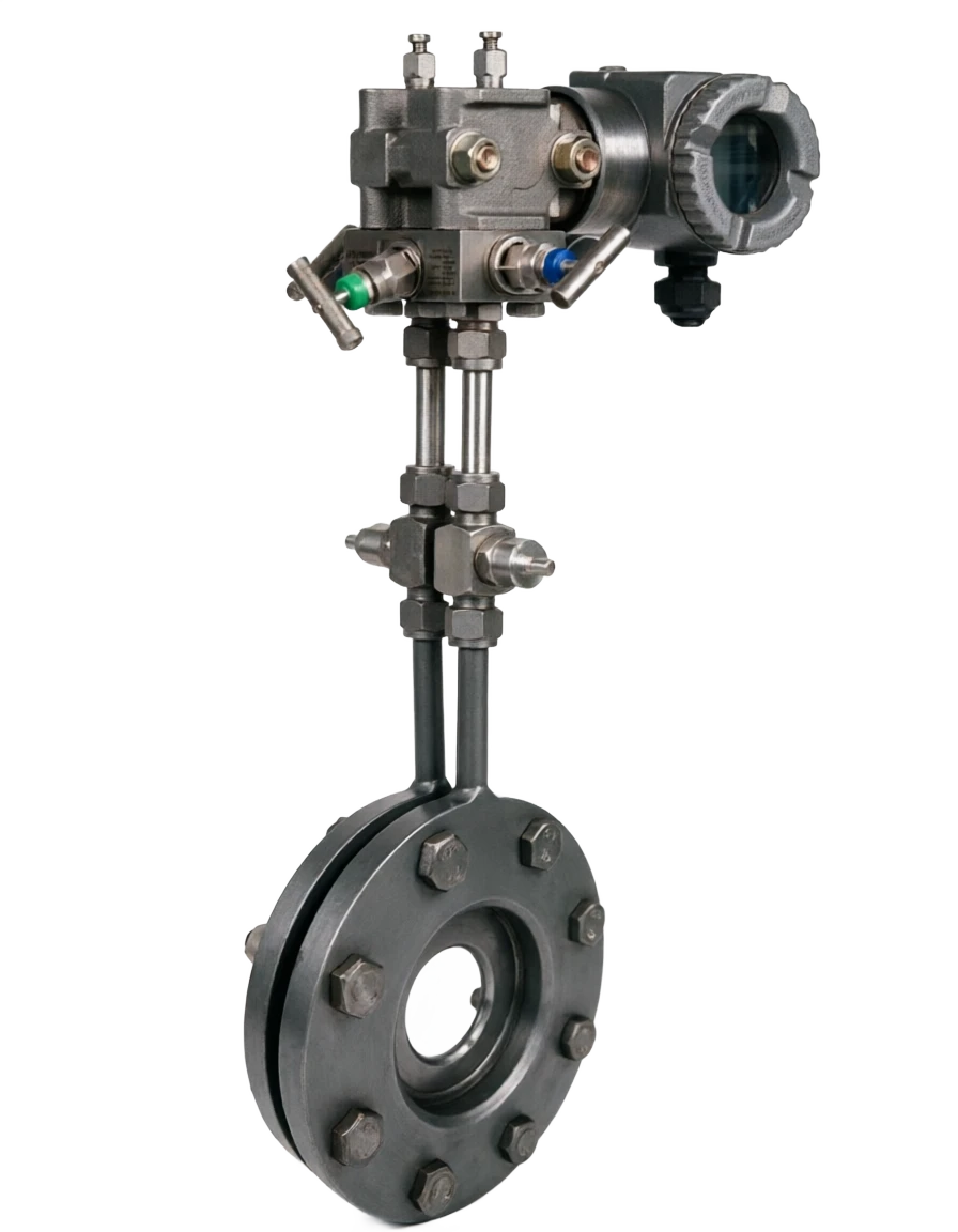
The pressure-trading circuit (the porosity plate + the pressurer) is controlled (the pressurized tube + the trivalve group) The Flow-Clock Pile of the differential transmitter is composed of, and is composed of, three major components, and completes the flow calculation and display of the secondary instrument (flow calculator/DCS).

3 Triple valve 2 extract pressure 1 Pyreboard primary component standard pressure mode D-D/ 2 Pull it up. 1 D, downstream. 0.5 D is the largest pressure difference, special case.

4-worst transmitter H (high pressure side)/L (low pressure side) output 4 - 20mA ∝ΔP

Five secondary meters/accumulations, squared temperature compensation, showing instant/cumulative flow.

Sequestering devices

Function and description: structure of upper-downstream pressure from perforation plate; split-point pressure, French pressure, D-D/2 pressure

Disk Transmitters

Function and description: Convert the pressure difference ⁇ P to a 4-20mA standard signal; smart-type output differential + static pressure + temperature (multivariant)

Control line

Function and description: The pressure tube connected to the pressure-cutting vent and the transmitter needs to be secured as non-concumbered, non-aqueous (liquid)/no-aqueous (gas detector)

Flange pressure

Repression position: ±25.4 mm (1 inch) at the end of the perforation plate Characteristics and applications: common in Europe and America, convenience of installation, beta narrow application

03

TECHNICAL GUIDE

Advantages and disadvantages

Main strengths

Main limitations

Highest level of standardization

The pressure is high.

Press GB/T2624/ISO

The one who's holding the margin.

5167 Manufacturing installation, which can be established without a streaming mark

20% 80%, which is the highest energy-consuming flow factor, and the number of streams is smaller.

Square root characteristics, scale scale ratio only 1 : 3 ~ Simple and reliable structure: non-motor components, pure mechanical festivals 1 : 5 Fluids, long-term stable durability medium accuracy: ±1.0% ~±1.5% , and by installation, low price: very low cost of throttle-savings, particularly the wear and tear of large pipes, which affect the economic straightness of their sections: upstream demand 10 ~ 44 D. Wide media for downstream application: gas, liquid, steam (single phase) required 5 ~ 8 D, high temperature pressure applies to wear and tear/clogged: sharp edges of the perforation plate are worn, and the range of ducts applied to the dirty pollution medium is large: DN50 ~ DN1000 The insertions can be more complex to maintain by plugging the pressure vents: catheters, trivalves, mesh technology mature: 100 years of application history, data evaporation/symmetric, winter freezing, good interchangeability sensitive to pulses: flow pulses magnify square root to ease examination: perforation plate can be replaced and transmitters can be calibrated online.

04

APPLICATIONS

Application area

(metametric mainstream)

Oil and gas

Long pipeline, wellhead, refinery hydrocarbon metering (traditional trade)

Petroleum chemicals

Process pipe line flow, gaseous liquid vapour measurement

Electricity industry

Steam, water, condensation, fuel metering

Vapour measurement

Saturation steam, overheated steam (compensated for temperature)

Gas pipeline

Urban gas gate, break-off station measurement

Metal and metal

High-tore gas, coil coal, gas, oxygen, nitrogen measurements.

Drain it.

Large-diameter water conveyance and water treatment plant inlet and outlet metering

Scientific experiments

Fluid mechanics experiments, standard flow devices, trace sources.

05

TECHNICAL SPECIFICATIONS

Technical specifications

A summary of the main technical parameters of the protection level transvestite IP65 / IP67 typical flow range (liquid, DN50 ~ DN500, beta = 0.5)

DN500190 ~ 300016 ~ 100 About 8 ~ 50

Notes

The above table shows estimates, and the actual flow range is determined by the aperture ratio of beta, the range of the variable, and the density of the medium.

Technical parameters · Parameter item / specificationCross-reference
Parameter ItemSpecifications
Applicable pipe pathDN50 ~ DN1000 (standard porosity); Voncho/nozzle can be larger
Process medium temperature50 ~ 550 °C (by material and pressure)
Accuracy class±1.0% ~±1.5% (Standard Hole, fully marked ±0.5%)
Turndown ratio1:3 ~ 1:5 (square root characteristics)
Aperture ratio, beta0.2 ~ 0.75 (beta = d/d, best 0.4 ~ 0.6)
Pressure tapping methodAngular / Frank / D-D/2 pressure
Accompanying pressure transporter4-20mA HART, range 0 ~10 kPa ~ 0 ~ 250 kPa (modifiable)
Signal output4-20mA、HART、RS485(Modbus)
Technical parameters Common diameter DN / Flow range (m³/h, water)Cross-reference
Common Passage DNFlow range (m³/h, water)Common differential pressure ⁇ P (kPa)Pressure estimate (kPa)
DN805 ~ 8016 ~ 40About 8 ~ 20
DN15018 ~ 28016 ~ 60About 8 ~ 30
DN30070 ~ 110016 ~ 100About 8 ~ 50
06

SELECTION GUIDE

Selection Guide

Select 5-step method + amplifier 1 Fluctuation device type is larger than the eccentric plate ±1.5% ~±2.0% Aerobic bubble-containing liquids/liquid-containing droplets2 in comparison with main flow meters, medium gas/liquid/vapour/liquid/vapour only electrical liquids are the main 3 media and the high temperature media of the condition selected (in the case of the main flow meters) >400℃ The selection of high-temperature alloy plume + high-temperature pressure material versus seal 4 perforate to beta

  1. 01

    65 ~ 0.75 Small, low-permit pressure, low-flow 5 differential transmitters and compensation configuration of remote-controlled smart transporter HART+ RS485 + Wireless transmission shall be accompanied by temperature pressure for the remediate body and steam; 3 An impurity medium shall be replaced by a round hole plate or nozzle; 4 is sensitive to pressure damage or has a higher rate than required

In the event of a crisis, priority is given to vortex, electromagnetic, ultrasound, etc.

© 2026 Summary of flow metering techniques . 6 Chapter

  1. 01

    1 Clear media gas/liquid/vapour single phase, cleanliness

  2. 02

    2 Determination of pipe routing and β DN50 ~ DN1000 β = 0.4 ~ 0.6

  3. 03

    3 Selected throttle type Standard hole plate Nozzle/Tunecree
  4. 04

    4 Decorated extractions Angles/Franc/D/2

  5. 05

    5 spread transmitter Scale + temperature supplementation

  1. 01

    Selecting Hints

    -pore plate

  2. 02

    (b) The most suitable for a single phase, allowing for a certain amount of pressure, requiring standardized de-marking, low pressure in a large tube diameter;

Selection Guide . Type / CompressionCross-reference
TypePressurePrecisionApply scene
Nozzles (ISA 1932)Medium±1.0%~±1.5%High-speed air currents, small particles, high-temperature vapours
Round hole plateLarge±1.5%~±2.0%Smuggling medium (gas pipe) with small impurities
Selective guide · Contrast / Perforate (discretion pressure)Cross-reference
ComparativePyramid (discretion)Turbo Street.EMPLOYMENTUltrasound
Turndown ratio1:3~1:5 (small)1:10~301:20~301:100
Precision±1.0~1.5%±1.0~1.5%±0.5%±1.0%
PriceLowMediumMedium HighHigh
Selective Guide · Media Type / Recommended ConfigurationCross-reference
Media TypeRecommended ConfigurationKey considerations
Natural gas (trade)Standard Plugin + Multivariant Transmitters + Flow ComputerAmended by AGA-3 standard, compression factor
High stoves/calciners gasRound hole plate + Dust removalCaramel, dust, round hole plate
Chemical Corrosion mediaHaq alloy/Monnell complate + diaphragm transducerPreservative, isolation fluid
Selective Guide Aperture ratio beta / pressureCross-reference
Aperture ratio, betaPressureTurndown ratioApplication of the recommendations
0.4 ~ 0.6 (recommended)MediumMediumMost commonly used, integrated best.
Selective Guide · Apply scenes / Recommended configurationCross-reference
ApplicationsRecommended Configuration
Gas measurementFragmenter + Pressure Transmitter + Temperature Transmitter + amplifier
Gas trade measurementMultivariant Transmitters (discretion + static + temperature combined) + flow computer (AGA-3)