PRODUCT TECHNOLOGY

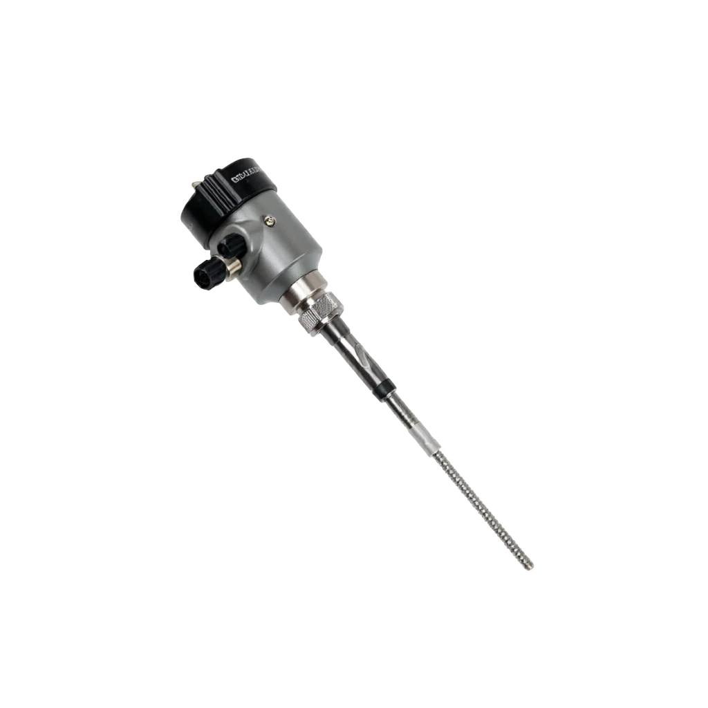
Radio-frequency conductor-type location controller

Operating principle

Radio frequency conductor, position controller.

At the core is a high frequency (HF) communication bridge consisting of a measurement electrodes (probes) and reference electrodes. The arm of the bridge is an equivalent electrical conceiving unit formed by the detector, and the arm is a fixed baseline conceiving unit within the instrument, which transmits a high frequency radio frequency signal (approximately 100 kHz ~1 MHz) to the bridge, and the bridge is in a balanced state with no signal output when the probe is not covered by material; When materials come into contact with the probe, the observed side-section of the capacitor, the resistance (synthesis) changes, the bridge deviates from the balance and the instrument detects a telecommunications signal that is proportional to the change in the location. The radio frequency conductor is called "radio frequency conductor" because it measures both the G (real) and the B (fiction) electron. The medium type and the level of electrodes are different, and the corresponding symmetric values vary. The instrument is adjusted by the self-adaptation threshold and sensitivity, and can be adapted to multiple conditions.

  1. 01

    • Installation of a reference electrode around the measuring electrodes at a height consistent with measuring the electrodes, symmetrically connected to the bridge by sample resistance ;

  2. 02

    • The power of the driver at the same level and with the same range as the probe is applied to measure the electrode, and to keep the charge between the shield and the probe to zero, avoiding the adhesive layer generating a congenial current.

  3. 03

    • At the same time, measure the electrical capacitor (fiction) and the resistance (real), separate the attached material from the actual material signal, and make a valid distinction between the "mounted material" and the "real contact material" location signal.

  4. 04

    1 . Radio frequency incentive source . Generate 100 kHz~ 1 MHz high-frequency sine signal feed into the bridge

Radio-frequency conductor position controller selection support

Provide survey missions, media and installation conditions and obtain product configuration advice.

Contact us
Radio-frequency conductor position controller Technical description

TECHNOLOGY & APPLICATION

Understand the principles, the exact selection.

From measurement principles to field applications, the technical features and selection elements of the radio frequency conductor are understood.

01

TECHNICAL GUIDE

Overview

The RFAdmittance LevelController is a place-detection instrument based on the principle of high-frequency bridge balance, which was pioneered and extended to the global industry by such United States instrumentors as Drexelbrook. It determines whether the material touches the measuring probe by measuring the conductive changes (conductor + electric) on the arm of the conceiving group in the bridge, thereby giving a position control signal, which can be used as a point switch for upper, lower alarm or pump valve connection control, and can be extended to continuous position count output of 4-20mA.

The biggest breakthrough in radio frequency conductor technology compared to the traditional capacitor control is the introduction of the "Reference Ether + Block Drive" adhesive compensation circuit. It treats the laminate layer as an "additional capacitor" that strips the laminate signal from the measurement signal by reference electrodes and synchronous shielding, thus allowing stable and reliable work even under the condition of the detectable medium, adhesive, high viscosity, corrosive work, which greatly expands the industrial landscape of site control.

Main features

Developmental progress

Radio-frequency conductive technology originated in the late 70 of the last century, and was rapidly spreading in petrochemical, electrical and metallurgical industries, as it breached the application bottlenecks of the capacitor tablets that were vulnerable to the adhesives. Since the 90 of the last century, our country has introduced and digested absorption, is now fully domesticized and exported in large quantities to countries along the " Way Forward " .

General description · Serial number / Main featuresCross-reference
Serial numberMain featuresBrief description
1Anti-set material, anti-fouling.The unique "Reference Ether + Block Drive" compensatory technology that eliminates the impact of the probe.
2Apply broad mediaLiquids, slurry, particles, powder, strong corrosive, strong adhesive media can be measured
3Simple and reliable structureInactivated parts, probes form in one form, long-term maintenance is avoided
4Flexible installationVarious forms of top insertion, side-loading, tilting, external postage, etc., adapted to various packagings
5High value for moneyLower price of high frequency (HF) position indices, such as radar, ultrasound, and better conditioned
6Multiple Output ModesRelay / 4-20mA / bus output, directly to PLC / DCS
02

MEASUREMENT PRINCIPLE

Operating principle

2.1. Bridge balance principle

At the core is a high frequency (HF) communication bridge consisting of a measurement electrodes (probes) and reference electrodes. The arm of the bridge is an equivalent electrical conceiving unit formed by the detector, and the arm is a fixed baseline conceiving unit within the instrument, which transmits a high frequency radio frequency signal (approximately 100 kHz ~1 MHz) to the bridge, and the bridge is in a balanced state with no signal output when the probe is not covered by material; When materials come into contact with the probe, the observed side-section of the capacitor, the resistance (synthesis) changes, the bridge deviates from the balance and the instrument detects a telecommunications signal that is proportional to the change in the location.

The instrument is adapted to a variety of conditions, as the electron G (real) and electron B (fiction) are measured simultaneously. The medium type varies from one to another, the electrode-mounted material is different, and the corresponding conductivity values vary.

2.2. Method of compensation for anti-mounted material

The traditional capacitating tabler can only measure changes in the capacity of the electricity, and the attached material forms an additional capacitation Cb on the probe, and the capacitation C0 when the material touches.

The radio frequency-guided sub-position controller uses two core compensatory techniques:

2.3 Signal processing and output

The detected internal MMU/DSP for the numeric numerator of the numeric change signal is then compared with the user-set high-to-low-gate threshold after magnification, filtering, flow management, A/D sampling and algorithm processing. When the conductor passes the threshold, the output corresponds to the high and low level or relay action, while the panel indicator gives a position status indication. Controller-type instruments are usually equipped with a CCD digital tube/Line crystal screen that displays current conductive values, location status and alert information on site.

2.4 Workflow mapping

Motion of work . Technical / PrincipleCross-reference
TechnologyRationaleEffects
Reference electrodes compensationAdd a reference electrode around the measuring electrodes that corresponds to the measuring electrodes at a height of the electrodes, with symmetrical access to the bridge by the sampler of the anti-second.Elimination of ambient temperature, power noise and external electromagnetic interference
Block drivers compensationWe're going to outsource a shield layer to measure the electrodes and impose a power drive at the same level and in the same range as the probe.Keep the shield and the probe to zero, avoid the hanger layer producing a perceptible current.
Electronsysyncmetric measurementsAnd measure both the capacitor (fiction) and the resistance (real) to separate the attached and the real material signals.It's a very effective distinction between the "mounted" and "real contact material" location signals.
Motion of work . Step / ActionCross-reference
StepsActionsAnnotations
1Radio frequency incentive source100kHz ~1 MHz high frequency sine feed into the bridge
2Bridges are unbalanced.Material contact, poaching, equilibria, poaching, output error signals.
3Signal processingZoom in, Stream, Filter, A/D conversion
4Anti-altrusion compensationReference electrodes + Block Drive to remove the adhesive signal
Motion of work . Step / ActionCross-reference
StepsActionsAnnotations
5Portage comparisonCompared with the set level of the field entrance
6Output ControlRelay insulation / 4-20mA / bus signal
7Show alarm.LCD / LED indicator location status and alarm
03

PRODUCT STRUCTURE

Product structure

3.1 Complete structure

It usually consists of the following parts:

The header (including display, operating panel, electrical cavity), process connection (screw, flank, carpentry, etc.), probe (measurement of electrodes + reference electrodes + shield), power and output modules. The surface is usually aluminum alloy or engineering plastics, protected by a level of IP65 - IP68, which is applied to industrial sites of a bad nature, such as outdoors, dampness, dust, etc.

3.2 Spectrum type and selection

3.3 Interconnection and Output Modules

The surface shell

Main function: Internalised main plate, display, operation button, electrical gas interface Typical material: clasped aluminium / engineering plastic / stainless steel optional

LCD/ LED display

Main function: Show the conductive value, position status, alert message Typical mass: LCD / LED number

Key / Dial

Main function: In situ setting sensitivity, delay, upper and lower limits

Electrical connection

Main function: Power / Output connection Typical mass: M20 / 1/2 "NPT/ Waterproof cable lock

Process connection

Main function: Connect to container / pipe Typical material: screw G1 / G2 / Frank DN50, etc.

Probes (measured polar)

Main function: Direct exposure to material, detection of changes in location Typical mass: 316 L SS / PTFE coating / Hapsy alloy

Probes (reference extreme)

Main function: Compensation of attached material and environmental disturbance Typical material: 316 L SS/ Co-prospecting material

Block Layer (drive)

Main function: Insulation of the wall, electromagnetic interference

Power module

Main function: Provide stable power supply to internal circuits 24 VDC / 220 VAC

Output Module

Main function: Relay / 4-20mA / bus output

Probe type

Structure module: Structural characteristics Main function: Typical application Typical material:

A pole-probe.

Structure module: Straight pole 316L stainless steel, with the desired length of the selected main function: liquid, slurry, bed / stand-by tank

Soft cable probe

Structure module: cable jacket insulation layer, bending deep into packagings, main function: large tank, high-level measurements

- The ceramic probe.

Structure module: PTFE / ceramics, resistant to corrosion, main functions: strong acid, strong alkalin, corrosive media

High temperature scout.

Structure module: Add heat-dispersion structures between probes and process connections. Main function: High temperature medium, high up to 450°C typical mass:

tablet / Hammer

Structure modules: Probes are flat or hammer structures. Main functions: particles, powder, substrate control.

Side-to-side scout.

Structure module: Side-loading screws / Frank, horizontal installation, main functions: interface measurement, upper / lower limit alarms

Relay Output

Channels: DDPDT x1 or SPDT x2 typical load capacity: 250 VAC / 5A or 30VDC / 5A application scenario: on/ below alert control, pump, valve connection

Double-line 4-20mA

Channels: 1 Channel Typical Load Capacity: 24VDC Ring Line Powered with Maximum Load 600 times

PNP / NPN transistor

Channels: 1-2 Channels Typical load capacity: maximum 100mA application scenario: direct-to-small relay, PLC digital input

Field bus

Channels: 1 Channel Typical Load Capacity: Hart / Modbus / Profibus-PA Application scene: Linked to PLC / DCS

04

TECHNICAL GUIDE

Analysis of strengths and weaknesses

4.2 Main shortcomings

4.1 Main advantages

- It's got a good anti-set, anti-fluent.

Description: The unique shield-driven technology that effectively eliminates jamming, clay, condensed water, especially suitable for water, mud, powder, coal, crude oil, sewage, etc.

Wide range of media application

Description: Liquids, slurry, particles, powder, strong corrosive, adhesive, strong viscosive media work reliably

Simple structure, high reliability

Note: No moving parts, no mechanical wear, long-term stable operation, average no malfunction time MTBF ≥ 100000 hours

Installation of flexibility and maintenance waiver

Description: Multiple installation methods such as top/ side/ tilt/ externals, installation debugging simple, essentially free of daily maintenance

Prices are high.

Note: far less expensive than radar, ultrasound positional index; as an ideal alternative at medium accuracy

Different modes of output

Note: relay / 4-20mA / bus is optional and easily integrated with PLC, DCS, SCADA

High temperature and pressure.

Note: Some models can work at 450°C/PN100, suitable for the harsh conditions at the industrial site

Low power, long life.

Note: Total power consumption is only 1 ~ 3 W, well below radar, ultrasound positionometer

Disadvantages and use restrictions

The length of the probe is limited.

Note: The length of the pole probe is ≤ 6 m, the flexible cable detector ≤ 30 m, restricted for hyper-long measurements.

Media-Media Constant Impact

Note: Measurement of low-media constant media ( ⁇ ) <1.5 ) or vacuum / gas scenes are not sensitive enough

EMPs are sensitive.

Note: Blocking measures are required in a strong electromagnetic environment; high frequency stoves, high power variants are required to be installed far away

We need to mark the scene.

Note: Different media, different conditions must be field-marked or affect accuracy

Not for closed high pressure vacuums.

Note: Partially closed containers, high pressure, vacuum not applicable; differential transmitters are recommended for use in hyperpressure settings

Temperature drift problem

Note: Extreme temperature environment needs to select high end models with temperature offset, and normal models generate measured drift

05

APPLICATIONS

Application area

It is widely used in various material stores, tanks, and battles at industrial sites because of its specific anti-alcoholic properties.

The following table shows the common application areas:

Typical application cases

(1) Lower and upper warning in clinker storage in the cement industry: a pole-based probe for upper and lower control of clinker levels in a stand-alone cement depot; in an internal powdered environment, the hanger 5-10 cm remains reliably identifiable as a result of the use of shield-driven compensation.

(2) Chemical Response Pu-Line Alert

Use strong acid detectors (Haps alloy + PTFE overlay) on PTFE liner, control upper and lower limit fluid levels on the PTFE and connect to emergency emission valves.

(3) Control of powdered coal ash storage at fire plants

Installation of radio frequency conductor counters at the top of the negative pressure warehouse as a control signal for the ash-discharge valve connection, which achieves automatic ash discharge.

(4) Control of pharmaceutical fermentation cans

Use of polished probes in fermentation tanks that meet the GMP sanitary level requirements to control the fermentation fluid level and upper and lower limits of the foam interface.

Chemical / petrochemical

Application scenario: upper and lower limit control of reaction plains Typical media: organic solvents, acid, crude oil, catalyst slurry

Metal / Steel

Applied scenes: material position, mineral powder storage detection

Electricity / Energy

Application scenario: ash silo, ashbaum, coal silo Typical mediums: ash, platinum, powder, gravel

Cement / Building Materials

Application scenario: cement storage, raw material warehouse, clinker warehouse

Food / Beverage

Apply scenario: sugar cans, malt silos, feedstock silos

Pharmaceutical/ Biological

Application scenario: feedstock, buffer, fermentation tanks Typical media: pharmacological, cultured, suspended

Environmental / Water Treatment

Application of scenes: sewage, sludge, pots

Paper / Pulp

Applying scenarios: slurry, black tank, white pool

Food / Feed

Apply scenario: grain, flour, prop: typical medium: wheat, corn, beans, tweed

Plastic / Rubber

Application scene: powder storage, plume, upper material control

06

TECHNICAL SPECIFICATIONS

Technical Parameter Table

6.1 General parameters for the whole machine

6.2 Accuracy and reliability parameters

6.3 Application of electrical parameters for media

Table of technical parameters · Parameters / Technical indicatorsCross-reference
ParametersTechnical indicatorsRemarks
Measurement principleRadio-frequency-guided nanobridge balance + Anti-mounting compensation—
Measure ObjectLiquid / Slurry / Particle / Powder / Strong Stick to Media—
Probe lengthBar: 0.1~6 m; Soft cable: 1~30 mMatch on a needs basis
Process connectionG1 / G2 screw; DN50 / DN100 Frank; 1 "~4" NPT optionalBy media and packaging
Power supply24 VDC ± 10% / 220 VAC ± 20% OptionalAn optional for width input
Work≤ 3 WTypical 1-2 W
Output MethodRelay DPDT x 1 / SPDT x 2; 4-20mA two-line; Hart / ModbusOptional by Model
Relay capacity250 VAC / 5A,30 VDC / 5ADisable load
Response time≤ 1 s (modifiable 0.5 ~ 30 s)It's set.
Sensitiveness0.5~500 pF, 16 modifiableOn-site reconciliation
Process medium temperature40 ~ +450 °C (tempor-resistant)Slotting by Model
Ambient temperature40 ~ +70 ℃—
Operating pressure0.1 ~ +10.0 MPa (to process connection specifications)—
Ingress protectionIP65 / IP66 / IP68By Model
Explosion protection markingEx d IIB T4 / Ex d IIC T6 / Ex iIC T6 (by model)—
Housing materialArgument/ Engineering Plastic / 316L SS optional—
Probe material316L SS / PTFE / Hapsy Alloy C / titaniumPress Media
Display typeLED / LCD Digital tube / LCD Chinese displayBy Model
Electrical connectionM20 / 1/2 "NPT/Waterproof cable locksPress the order.
MountingTop/ Side / Tilt / External / French installationPress the scene.
Weight2~8 kg (by probe length)—
Technical parameter table · Parameter / IndicatorCross-reference
ParametersIndicatorsTest Conditions
Switch action error±1 pFTemperature pressure cleans the water.
Repeatability±0.5 pF10 consecutive times
Response time≤ 1 sDefault Settings, Reconcile
Action Delay0.5 ~ 30 s truncableOn site adjust to media
Insulation resistance≥ 100 MΩ500 V mega-eats
Pressure resistance2500 VAC / 1 minPower-to-ground stress.
MTBF≥ 100000 hoursAverage no-facilities time
EMC CompatibilityGB/T 17626Industrial-level electromagnetic compatibility
Temperature drift≤ ±0.5 pF / 10℃Temperature compensation type
Media TypeMedia constant ⁇Typical applicationSensitivity advice
Liquids (water)ε≈ 80Water, sewage, acid.Medium / High-level sensitivity
Liquids (oil)ε≈ 2~10Oil, diesel, cooking oilVery smart.
Slurpee.θ > 30%Catalytic, pulpVery smart.
Particle materialΦ > 5 mmCoal blocks, ores, stones.He's a smart guy.
Powder.Φ < 1 mmCement, flour, coal powderHe's a smart guy.
Strong sticky adhesive.It's sticky.Brackets, rubber particlesAdd a shield drive
07

SELECTION GUIDE

Select Table

7.1 Naming rules

Selected examples

RF-T-R-0500-T3-P3-L-D-6 means radio frequency conductor, top-loader, relay output, probe length 500 mm, temperature 250°C, pressure 4.0 MPa, 316L material, blastproof type, IP66 protection.

7.2 Summary of commonly used models

Selective Table . Code Section / Code ExampleCross-reference
Code segmentExample:What's code for?
RF-RFRadio-frequency conductor series code
- TypeT/A/S/WT top/ A side / S pole / W soft cable
- OutputR / I / HR Relay / I 4-20mA / H Hart
- Inspector.0500Four digits, in mm = 500 mm
- TemperatureT1/T3/T4T1 100℃ / T3 250℃ / T4 450℃
- Pressure.P1/P3/P5P1 1.0MPa / P3 4.0MPa / P5 10MPa
- MaterialsL/H/TL 316L / H Haps Alloy / T titanium
- Bomb protection.N/D/IN / D barlast / I Benan
- Protection5/6/85 IP65 / 6 IP66 / 8 IP68
Selective Table . Model / Spectator TypeCross-reference
ModelProbe typeOutputTemperature rangePressure rangeApplications
RF-TS-1000Stick 1 mRelays40~150℃1.0 MPaGeneral fluids are at the bottom of the line.
RF-TI-1500Array 1.5 m4-20mA40~150℃1.0 MPaContinuous location remote surveillance
RF-WR-3000Soft cable 3mRelays40~150℃0.5 MPaSilo, powder high control.
RF-AR-0800Side-loading 0.8 mRelays40~250℃4.0 MPaReaction zone, call the police.
RF-TH-4500Bar 4.5 mHart40~450℃10 MPaHigh temperature and high pressure continuous position
RF-WH-15000Soft cable 15mHart40~150℃1.0 MPaLarge tank continuous measurement
RF-SR-0500Flatbed DetectiveRelays40~120℃0.3 MPaPowder, particulate control
RF-AR-I-0800Side-pack 0.8m Benn.Relays40~200℃4.0 MPaChemical Flammable Explosive
08

SELECTION GUIDE

Selection Guide

8.1 Basic steps for selection

8.2 Model job recommendations

8.3 Selective care

(1) The length of the probe should be retained in excess

The normal duration of the probe = the height of the container - install the French height + 50 mm excess to avoid measuring the dead zone.

(2) The EMIM environment shall be selected for shielding cable placement and shall be far from the high power frequency variants, high frequency furnaces and, if necessary, metal casings.

( 3 Low media-based constant ( ⁇ ) <2 ) or the powder particles are smaller ( < 0.1 mm ) is recommended to select the "High Sensitivity + Block Drive" combination model.

(4) The blast-proofing scene must confirm the blast-proofing certificate number and grade provided by the manufacturer, and the power supply / output parameters are strictly wired in accordance with blast-proof specifications.

(5) Adequate installation space should be reserved for the site

Vertical space peripheries above the top flanges; ≥ 200 mm is reserved outside the side wall of the side container when the top time frame is loaded.

(6) For crystall-friendly, condensable media, the temperature-preservation/heat-accelerator drum should be added; the crystal thickness should be considered when choosing the poaching length.

(7) Periodic inspection of the surface hangers of the probe and, if necessary, electrical clean-up; periodic verification is recommended every 6-12 months.

(8) Cables and power supply sub-chutes should be installed to avoid co-opting with power cables; it is recommended that 24 VDC be used to isolate the power supply.

8.4 Summary

It is one of the most widely applied instruments in the field of site control, and with unique anti-mounting technologies it is capable of performing most of the top-down and bottom-limit control tasks on industrial sites. The selection needs to be combined with factors such as medium properties, temperature pressure, installation, output, and priority to be given to mature, well-established, applied and well-developed mainstream brands, and to maintain sufficient design sufficiency to ensure long-term stability.

Selective guidance · Steps / ConcernsCross-reference
StepsElements of concernCommon Options
1Media TypeLiquid / Slurry / Particle / Powder / Strong Corrosion / Visible
2Work temperatureLow ≤100℃ / Medium ≤250℃ / High temperature ≤450℃
3Work stress.Constant pressure / 1 MPa / 4 MPa / 10 MPa
4MountingTop/ Side / Tilt / Frank / External
5Output FormRelay / 4-20mA / Hart / Modbus
6Explosive protection requirementsNormal / Detonation / Bennan
7Ingress protectionIP65 / IP66 / IP68
8Probe material316L / Hapsy Alloy / titanium / PTFE overlay
9Probe lengthCalculated by container diameter / depth of insertion
10Sensitivity SlottingSelect by the media constant / holdup level
Typical Work StatusRecommended ModelRationale
Water / Sewage Level ControlRF-TS-1000 / RF-TI-1500The medium constant is large, sensitive, price economy
Esmoline / diesel fluid levelRF-TI-1500Small ad hoc frequency, high sensitivity, continuous output
Coal powder / Cement powder barnRF-WR-3000Soft cable deep into powdered bunkers; shield-driven anti-mounted material
Reaction PureRF-AR-0800Side-dressing Frank, temperature-resisting 250°C, pressure-resisting 4 MPa
Crude oil / heavy oil tankRF-WH-15000 + Hart outputLarge tank soft cable, televised.
High-temperature super-heated steam condensersRF-TH-4500Temperature-resistant 450°C, pressure-resistant 10 MPa
Strong acid / strong base tankPTFE package RF-AR-PTFEIt's corrosive. The probe is insulated.
Powder ash storage (power plant)RF-WR-3000-IP68Dust, humidity, IP68, high protection.
Coal block / Ore Substrate ControlRF-SR-0500 tabletThe flat-bed probe is resistant to shock and wear.
Pharmaceutical fermentation cansPhoto-ray RF-AR-PVDFGMP Health Level, Easier to Decontamination