PRODUCT TECHNOLOGY

Smart PID controller

Operating principle

Smart PID regulator .. working principles

The smart PID regulator is internalized by "simulating signal reconciliation + digital PID operation + continuous current output" three-layer structure: a front-end process measurement PV is being translated with a one-size-fits-all conversion and project conversion, and MMU runs PID algorithms by default, and is receiving control MV (0~100%), conversion of 16-bitDAC to transistor current source to 4-20mA output, and continuous drive of the implementing agency. A given value SV is from the machine's own key or remote simulation/communication channel.

  1. 01

    1 PV . mA / mV / V/ Thermal Peddler / Thermal Retardation Full Compatibility; 24-bit ⁇ - ⁇ ADC; Speculation Table; CJC Cold End Compensation; Linearization of the Project

  2. 02

    2 For value processing . Key given (two rows of LED number increases and decreases), remote given 4-20mA / 0-10V, Modbus communications given three optional categories; slope (Ramp) limit + upper/ lower limit

  3. 03

    3 PID Central . Location PID or Incremental PID; Parameter range P 0 ~ 999.9%, I 0 ~ 3600 s, D 0 ~ 3600 s; Positive/reverse effect; (a) Segregation of points; (a) Resisting saturation; Micro-column First + Un-prescribed mutation

  4. 04

    4 . Control algorithms enhanced . Self-refining (relay feedback/ critical scale method); parameter fraction (output-range segment mapping); dead zone and threshold limit; complex control (string/ front-off/ margin) software package

Smart PID controller selection support

Provide survey missions, media and installation conditions and obtain product configuration advice.

Contact us
Smart PID regulator . Technical description

TECHNOLOGY & APPLICATION

Understand the principles, the exact selection.

From measurement principles to field applications, the technical features and selection points of the smart PID regulator are understood.

01

TECHNICAL GUIDE

Overview

Smart PID regulator is a single circuit control instrument with PID operations at the core, which produces a continuous 4-20mA (or 0-10V) analogue signal. It compares process measurement signals PV with the SV given, by scale, points, calculus, output continuous current to the AV-minus-Veaver, and other implementing agencies, and constitutes the classic single circuit control program "Register + Executing Agency + Measuring Transmitters", which is the most popular on-site control in the process industry. (a) "Sister" type with the 49th Smart Server Control PID regulator (bit relay output): This is a gas-oriented / locator-enabled implementing agency, with higher continuous control accuracy; 49 for the touch-point electric implementing agency, with a simpler one-way cost and connection.

  1. 01

    1 Comparison with Smart Service PID (Page 49), DCS ReturnL card

1.2 A brief history of development

Overview * Project / AnnotationsCross-reference
ItemAnnotations
Product positioningOn-site single circuit controller: PID Operations + Continuous Simulation Output, the most popular "specified field control" pattern outside DCS centralized control
Core valuesContinuous current output accuracy (no location inner ring required); omnibus input overlay temperature/ pressure/ flow/ liquid level; self-regulating off-the-job coding parameters; PID control algorithm upgrades bring more stable control quality
Output FormContinuous 4-20mA (or 0-10V) output, continuous implementing agencies such as drive aerodynamic control valves, electrical converters, frequency transformers / voltagers
Implementation agency fitAerodynamic film control valves (Electro-Air Converter + Valve Positionor), electric control valves (inline locator), modular modulation speed (electrical currents given + detonating point), electron implementer controllers (self-enclosed ring)
Market patternsNational production is dominated by: Rainbow, Woo-tung, Far East, Fukuoka, etc.; imports are represented at the highest end by Yokawa, Fuji, Omlon, Honiwel; national production mainstream 1000-3000 and imports 5000-15000
Contrast DimensionsSmart PID Compressor (This Part)Smart Service PID (PART 49)DCS Back to the road.
Output FormContinuous 4-20mABitmap relay positive / invertedContinuous 4-20mA / bus
Implementing agenciesAerodynamics / with locator electrics / frequency convertersTouched electric (no locator)Gas / Electric
Control precision0.5 ~ 1 % FS (continuous reconciliation)1 ~ 2% FS (bit break)0.1~0.5% FS
Small flow reconciliationExcellent.General (fought limits on contact action)Excellent.
One-way investmentsLowerMinimum (no locator required)High (card + control station)
Engineering IntegrationDisk independent, debug and maintain simpleLoad up independent, drive the driveway directly.Control room centralized, centralized
Apply back-to-back scale1-8 Return to single-track programme economy1-4 return path, driver limited8 Economy above Road
PeriodPhaseTechnical characteristics
1960s-70sThe Aerodynamic and Electric DDZ AgeAerodynamics (0.14 MPa signal) + DDZ-II (0-10mA)/ DDZ-III (4-20mA) regulator; pure simulation (discharge + RC network) with difficult to copy parameters
Overview · 1980s / Start of the digital regulatorCross-reference
1980sNumber adjuster StartSingle-piece PID regulator begins to spread; simulation panel grouping (put-in parameters); phase increases significantly compared to pure simulation program stability and repetitivity
1990sSmartMPU achieves PID self-recommended (relay feedback method), fuzzy + PID complex controls; key-forming replacements; a universal input type appears
2000sFunctionally improvedDouble PV / Thread / Front Feed / Value Control package; MODBUS Communication Access to Input; Multiple Output Channel (Control + Transport + Alert) Independence
2010 to dateAdvanced algorithms and self-adaptationSelf-replacement upgrade to model adaptation; MPC (model prediction) preview function; OPC UA / MQTT straight-link cloud platform; integration with DCS simulation upgrade
02

MEASUREMENT PRINCIPLE

Operating principle

The smart PID regulator is internalized by "simulating signal reconciliation + digital PID operation + continuous current output" three-layer structure: a front-end process measurement PV is being translated with a one-size-fits-all conversion and project conversion, and MMU runs PID algorithms by default, and is receiving control MV (0~100%), conversion of 16-bitDAC to transistor current source to 4-20mA output, and continuous drive of the implementing agency. A given value SV is from the machine's own key or remote simulation/communication channel.

2.1 signal chain eight subsystems

2.2 Analysis of Key Rationales

Modus operandi . Serial number / subsystemCross-reference
Serial numberSubsystemFunctions and elements of achievement
1Almighty input PVma/mV / V / Thermal Peddler / Thermal Resistor Full Compatibility; 24-bit ⁇ - ⁇ ADC; spectrometer; CJC Cold End Compensation; Project Gradualization
2Value ProcessingThis machine gives three optional types of key (double LED number increases and decreases), remote 4-20mA / 0-10V, Modbus communications; slope (Ramp) limit + upper / lower limit bands
3PID Operations CorePositioned PID or Incremental PID; Parameter range P 0 ~ 999.9%, I 0 ~ 3600 s, D 0 ~ 3600 s; positive/ inverse; fraction separation; anti-saturation saturation; micro-column + less than full-micropression mutation
4Control algorithm enhancementSelf-refining (relay feedback/ critical mass); parameter fraction (output range segment mapping); dead zone and threshold limit; complex control (string/ front feed/ margin) packages
5Control Output16 -bit DAC+ transistor constant current 4 - 20mA Output (load) ≤ 500 ~ 750 Once; optional 0 - 10 V output;output limit 1 ~ 22mA (c) Available;NE 43 Fault Direction (Drive) 3.6 / 21mA Support
6Transport and Assistive Output4-20mA Transmit output channel (PV / SV / MV any forward); auxiliary switch input and relay alert output
7Communications and human interfaceDouble row LED display PV / SV; key-based grouping navigation; status light indicator running / alert / hand automatic; RS-485 (Modbus-RTU) communications; Ethernet selection
8Protection and diagnosisOutput limit bands; fraction resistance to saturation; self-refining compression determination; sensor breakline / short-circuit protection; parameter modification of permission classification and event recording
· Analysis item / Mechanism descriptionCross-reference
Analysis ItemScheduling
Close the loop.4-20mA output gas signal via electrical converter ⁇ Aerodynamic valve locator ⁇ The valve opening degree forms a closed loop; Unlike 49, "Inline Rings": the regulator only exports currents, the location closed rings are done by the locator, and the two functions are divided into two-stage indirect closed loops, "Electron to Air Signal to Location"
PID Physical significance of the three parametersP. Decision to balance response speed with steady state error (too strong oscillation, too weak response slow and less); I to eliminate residual differences (too long to introduce a fraction lag, too short to oscillation); D to provide reverse phase ahead compensation to inhibit rapid disturbance (too large to be sensitive to sampling noise)
(b) The principle of positive and negative action selection / positive effect (inverse deviation): PV ⁇ MV ⁇ (e.g. heat heater control - high temperature and increased heat); (b) Counteracting (positive deviation): PV ⁇ MV ⁇ (e.g. cooler temperature control - high temperature reduction cooling); The error caused the positive feedback to lose control - the grouping must be followed by a valve-direction test.Cross-reference
Positive and Counteracting SelectionPositive effect (inverse deviation): PV ⁇ MV ⁇ (e.g. heater heat - high temperature and increased heat); (b) Counteracting (positive deviation): PV ⁇ MV ⁇ (e.g. cooler temperature control - high temperature reduction cooling); The error caused the positive feedback to lose control - the grouping must be followed by a valve-direction test.
Self-regulating the rules.Follow-up feedback method: Composer enforces output ⁇ ( ⁇ test range), observes the equivalent oscillation of the PV between upper and lower limits, is revised to apply P/I/D by inverse critical gain Kc with critical cycle Tc (e.g. 30%) from the oscillation cycle to the Ziegler-Nichols formula.
Separating and saturationBlocking fractions (departure) when deviation is greater than threshold, reducing over-modulation; freezing build-up when output limit limits and deviation directions remain in place (resistence) and rapid departure from saturation areas in reverse response
Micro-point FirstPV only (not SV); default grade leap changes do not trigger a significant impact on PI output, effectively inhibiting a given value disturbance, the engineering compromise commonly used in PID
03

PRODUCT STRUCTURE

Product structure

The whole machine is a plate (DIN standard 96 x 96 mm or compact 48 x 96mm) instrument, with two rows of LED and keys in front of the plate, the core consisting of input plates, the master control panel and the output panel, and the signal and output channel is designed to reduce interference by the EMC-designed partition.

Analysis of strengths and weaknesses

4.1 Advantages

4.2 Disadvantages and responses

Front panel.

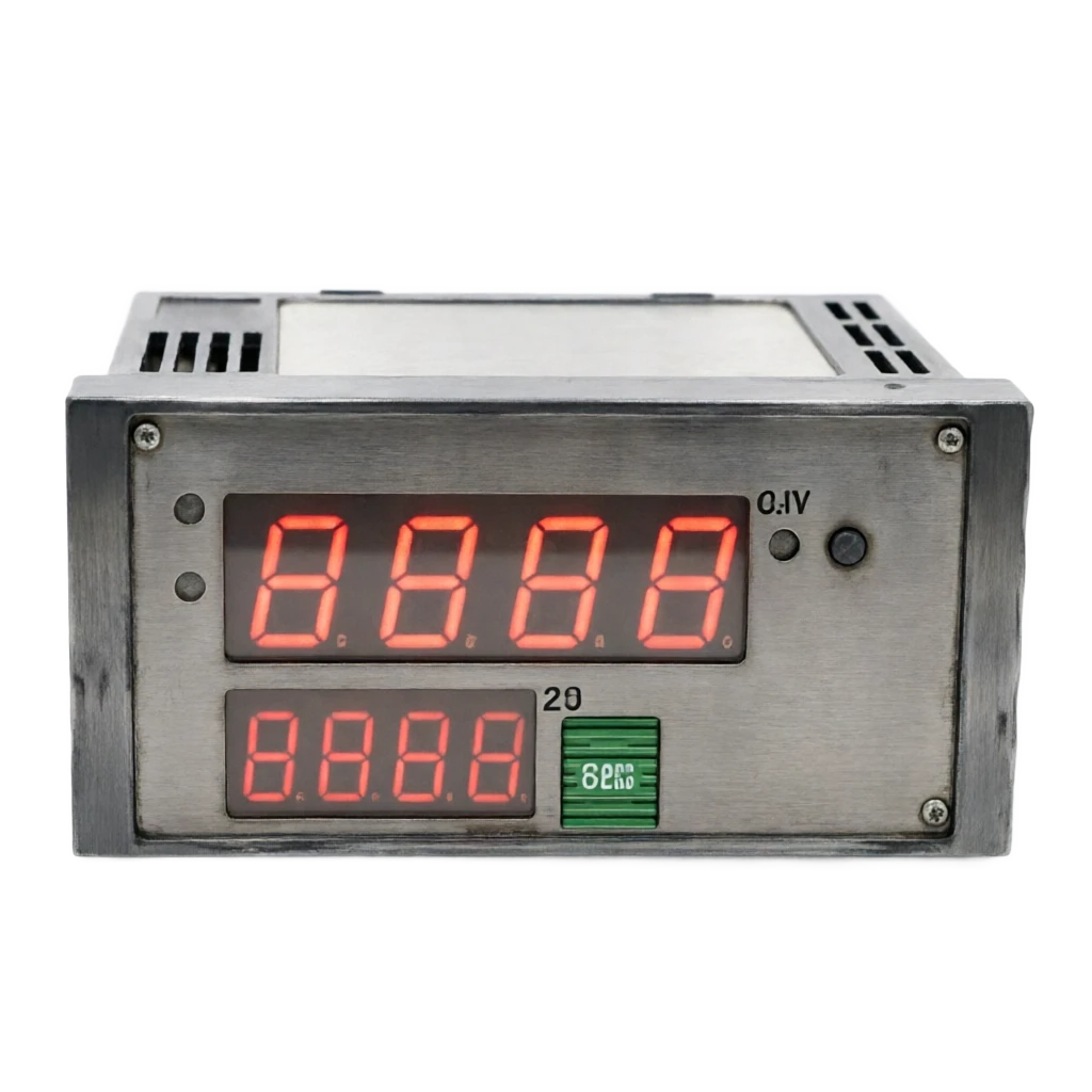
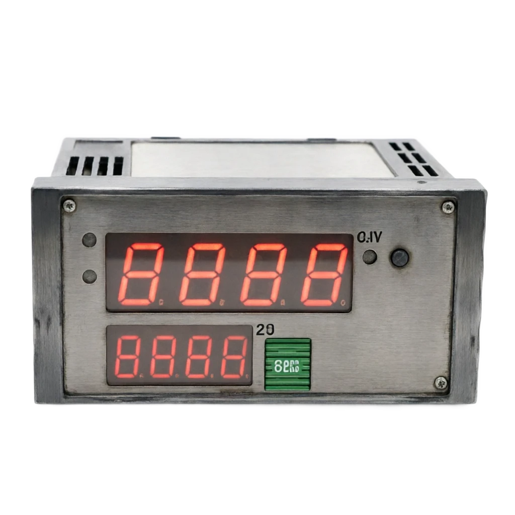
Composition and function: Double row four-bit LED (prescript PV/ by-speech SV or MV); Automatic / Manual key, add or decrease key, group key; Status light (Auto/ Manual / Alert / Lower and Lower Level of Vault)

Enter a signal panel

Composition and function: A MasterCriteria + Remotely Give SV Channels; TVS Anti-Input Pressure and ESD; Scoresheet and Project Volume Linearized MMU Solids

Console

Composition and function: MMU runs PID, self-regulating, communication and grouping; parameter EEPROM power outages; real time clock for event recording

Output Panel

Composition and function: DAC + constant stream output 4-20mA (or 0-10V); load self-resilient; output limit band and NE 43 down direction

Sending and calling the police

Composition and function: PV / SV / MV All Selection 4-20mA Transmit output; 2~4 point relay alert (PV upper and lower limits, deviations, sensor failure)

Communication interface

Composition and function: RS-485 (Modbus-RTU) standard; Ethernet (Modbus-TCP) selection; OPC UA / MQTT cloud interface in the new generation

Power unit

Composition and function: 85 ~ 264 VAC extenuating or 24 VDC; whole power ≤ 5 W

End subsector

Composition and function: Partition endpoint setup: input/ output/ transport/ communications/ alarm/ power; panel protection IP54 (sealed)

Evolutional trends

Structure: Description Composition and function:

MPC Preview

Structure module: A simplified version of the MPC algorithm embedded in the General Compagner to deal with the big lag and multiple disturbances objects as PID upgrade options Composition and function:

AutoAdapt +AI

Structure units: Auto-adjusted parameters (PID self-recomposition based on a nervous network) for process response, non-linear object composition and function:

Cloudic Parameter Management

Structure units: OPC UA / MQTT straight-on cloud, parameters and formations sink from engineer stations down to cloud mass management Composition and function:

Smart diagnosis

Structure module: Control quality assessment (IAE / ITAE indicator), parameter health rating, sensor drift detection and implementing agency dead zone warning Composition and function:

Continuous control accuracy

Note: 4-20mA continuous signal is fine, with no-place-to-space loss; small flow fine-regulating power is much better than the 49th place relay type

ABW coverage

mA / mV / V / TC / RTD fully compatible; temperature / pressure / flow / fluid / location / composition unit regulator fully covered

PID algorithm mature and stable

Positioning / Incremental / Thread / Front-Living / Value Control algorithms have been tested back-to-back; engineering techniques such as micro-column, fraction separation, saturation, limit limits are available

Self-restruction savings.

Relay feedback / critical scale self-recommended P/I/D available within 30 minutes; waiver of manual overtime; automatic optimization of parameters by object characteristics

Appropriately mature implementing agencies

4-20mA is a unified signal system for global process control, with direct connection of aerodynamic valves, electrodynamic valves with locator, frequency transformers, voltage adjusters, electronic controllers.

Automatically and in a flexible form

Hands / Automatic Two-way Undisturbed; Key or Remote Grouping Parameters; Fulfilled Transmission Output and Alert Channels

Economy and maintenance simplicity

Single price 1000-3000 is much lower than DCS; disks are installed independently, failure location and replacement simple, suitable for single circuit retrofit between small and medium projects and old devices

Disadvantages and use restrictions

Entries closed with external position

Description and response measures: Aerodynamic valves must be equipped with electrical converters + valve locators; electric valves must be built-in locators; chains longer than 49 "Container's internal position closed" and debugging and failure points increased - redundancy by return criticality

One-way pattern

Description and response: One turn, one turn back time, and a high burden of maintenance; 8 above the turnback should be directed to the DCS / small PLC programme

No-drive power capability

Description and response measures: Output is 4-20mA weak signal, not direct driver contact; not like 49th direct drive power - this table applies to the chain of execution with locator or electrical conversion

It's a good and negative choice.

Description and response: a misorganization can cause a positive feedback to lose control; a test action test of the valve must be performed on site (addition or decrease of the MV observation valve)

Saturation and Hypersonic

Description and response measures: Accumulation of points leads to a lag in the reverse response when the major deviation exists for a long time and the implementing agency reaches the limit; enable the separation of points with the saturation function is mitigated

The effects of the big lag object are limited

Description and response measures: Pure PID limited quality of control over large lag objects (temperature, fluid level); MPC algorithms or serial programme improvements; or selected upgradeer type with MPC preview

It can't be used on Ben Ann's way back.

Description and response measures: instrumentation not certified; return route to hazardous area shall be detached / shell-enriched as a whole or installed in safe zone control room

04

APPLICATIONS

Application area

Smart PID regulators are used mainly in single-way process control situations, which are end-ups of aerodynamics/positioners/frequency transformers, and typically in the following industries.

5.1 Five typical application models

Petroleum chemicals

Typical application scenario: Reaction pyrotechnic (vapour valve), reflow of distillation towers, tank pressure / liquid level Common configuration: all-power input, serial / front feed package

Electricity

Typical application scenario: Oxygen-water level regulation, carving vacuum, auxiliary cooling water temperature, frequency transfer pumps Common configuration: frequency-moder currents given + detonating point

Metallurgy

Typical application scenario: heater temperature (gas valve), average furnace pressure, roller-line cooling water flow Common configuration: Aerodynamic control valve + serial level (temperature - flow)

Construction materials and cement

Typical application scenario: CKT tail temperature (coal valve), raw material formulation, wetting of the wet tower Common configuration: front feed + PID anti-turbation

Water treatment

Typical application scenarios: additional dose (measurer valves), exposure wind (frequency), liquid level of the clean water pool

Pharmaceuticals

Typical application scenario: fermentation tank temperature (with water valves), fung cabinet FMP online, set recorder to achieve batch recorder

Warm.

Typical application scenario: temperature of water supply at heat exchange stations (electrical control valves), temperature of air conditioning tanks, new wind doors Usage: economy 48 x 96 compact size

Mode

Backway composition.

Basic one-way circuit.

PV Sensor ⁇ 4-20mA ⁇ electric-gas converter ⁇ aerodynamic valve locator ⁇ most commonly used form of valve; positive-reaction by circuital properties selected; self-replacement of yield

Thread Control

PID output is used as a side tune SV; side-drive valve; side-drive is used to slow variable, such as temperature / mass, side-deep to fast variable, such as flow improves disturbance response; main-deep continuum is sufficient and the side-drive is required to respond quickly

Front feed control

Feed channel output before disturbance and PID feedback output superimposed and drive valves Compensated for detectable disturbance; complementary to feedback PID

margin control

Main mass is measured by a margin factor; main amount tracked from the drive loop, fuel / air margin, formula plus drug, etc.

Valve Range

Output 4-12mA drive A valve, 12-20mA drive B valve A regulator controls two valves and extends control range

05

TECHNICAL SPECIFICATIONS

Technical Parameter Table

The following table shows the typical specifications of the smart PID regulator (96 x 96 disks for general purpose), which are based on sample manufacturers.

  1. 01

    Select Table

The price is the price of a single RMB.

7.1 Order code structure (example 8 bits)

  1. 01

    Selection Guide

8.1 Ten Elements of Selected Decision-Making

8.2 Typical scene selection path

8.3 Four procurement acceptances

Summary

Smart PID regulator and 49th smart server control PID regulator form a "sister" type - a continuous implementing agency such as aerodynamics/with locator electrics/frequency transformers (control is more accurate, but requires external electrical conversion + valve locator or locator-type valves); 49 for the subject-matter electric implementing agency (inline ring, lowest one-way investment). Selective logic: First, the type of implementing agency, second, the need for control precision, and third, the availability of locator or electrical converters. This series shows the continued expansion of the family of record and control instruments, followed by alarm devices, patrol devices, etc.

Technical parameter table . Serial number / parameter itemCross-reference
Serial numberParameter ItemTypical specification
1Enter PVParity input: 4 - 20mA / 0 - 20mA; 0 - 20 mV ~ 0 - 20V; Thermotogram K/S/B/R/E/J/T/N; Thermotically Resist Pt100 / Cu50; Sampling cycle ≤ 0.5 s, Precision 0.2% FS
2SVThis machine is given with keys (two rows of LED plus or minus); remote with 4 - 20mA/ 0 - 10 V; communication with (Modbus); given with an 0 ~ 9999 unit/ seconds
3Control OutputContinuous 4 - 20mA (Hands) ≤ 500 ~ 750 (a) Once; or 0 - 10 V output;output limit 1 ~ 22mA Available; Fault orientation ( 3.6 / 21mA )NE 43 Support
4PID algorithmPosition PID/ Incremental PID; P 0 ~ 999.9% 、I 0 ~ 3600 s、D 0 ~ 3600 s; positive and negative; micro-division; fraction separation; saturation; self-recommended (relay feedback/ critical scale method)
5Control precision±0.5% FS (continuously no dead zone of reconciliation); steady-state error ⁇ ±0.1% FS (when points are sufficient)
6Response and cycleControl cycle 0.1 ~0.5s; positive and reverse leap response times are determined by object and parameters
7Transmitter output4 - 20mA Transmit output 1 ~ 2 (PV/ SV/ MV optional); load ≤ 500 times
8Alarm outputRelays 2~4 points: PV upper and lower limits, deviations, sensor failure, control deviations too large; contact capacity 3A / 250VAC
9Communication interfaceRS-485 (Modbus-RTU) standard; Ethernet (Modbus-TCP) selection; OPC UA / MQTT selection
10Composite ControlThread / front feed / margin / double PV package selection; valve split output 4-12mA / 12-20mA
11DisplayDouble rows of four LEDs (prescript PV/ sub-spectrum SV or MV); valve percentage, running status, alarm lights
12Manual / automatic changeoverTwo-way Undisturbed; MV = Current Output (Tracking); Soft Manual (Addition/decrease) and Hard Manual Point
13Power supply85 ~ 264 VAC 47 ~ 63 Hz (typical); or 18 ~ 36 VDC; ≤ 5 W
14Environmental conditionsJob 0 ~ 50℃, Humidity ≤ 85% RH without Condensation; Vibration ≤ 0.1mm (10 ~ 55 Hz) Disk Load Environment
15Installation and protectionPanel DIN 96 x 96mm open 92 x 92mm (mainstream); compact 48 x 96mm; panel protection IP54 (sealed circle); outer depth ≤ 100mm
16Insulation and securityEnter / Output / Power Intersulation 1500V AC; compliant with GB / IEC disk device security standards
TrancheRepresentative brand and seriesTypical ConfigurationSingle-desk priceTypical applications
Technical parameter table · Imported high end / Trans-UT/ UP series, Fuji electric power PXR, OmlonCross-reference
High end of importTrans-ruy UT / UP series, Fuji electric powerer PXR, OmronCustom + MPC preview; OPC UA/ Ethernet; high precision / high stability5000-15000 yuanForeign investment projects, export packages, special certification
High-end domestic productionIon Yuen / Uyon / AI / FukuokaThread + front feed + margin package; self-refining; Ethernet; high accuracy 0.1%2500 to 5000 yuan.Important process circuits, ups, integration.
Domestic production standardsRainbow / Woo Power Base / Far Eastaltruistic input + self-regulating; double-spectrum + alarm; RS-4851000~2,500 CNYNew project main, generic, one-way
Universal national productionLocal instrumentator common seriesfixed input type; basic PID without self-regulating; key-based operation400-1,000 CNY.General circuits, renovations, budget sensitive.
bitsMeaningCommon take-up examples
1Broad categories of productsP = Smart PID Compressor (Continuous Output)
2Panel Dimensions9 (96 x 96); 4 (48 x 96); 8 (80 x 80); 0 (guided)
3Input typeX (Universal input); K/S/E/P (Designated fraction number); A (electricity)
4Output TypeA (4-20mA); V (0-10V); D (double output); F (frequency adapter)
5Call the number.2 / 3 / 4 (relays alert points)
6Communication interface0 (none); R (RS-485) E (Ethernet); C (OPC UA/MQTT)
7Algorithm PackageB (basic); S (string level); F (favour-receiving); R (margin); M (MPC preview)
8OptionsH (high accuracy 0.1%); V (valve fraction); T (track power); default base type
Technical parameter tables · Decision-making elements / Decision pointsCross-reference
Elements of decision-makingElements of judgement
Type of implementing agencyAerodynamic control valves, electrodynamic valves with locator, frequency transformers, electronics implementers ⁇ Continuous output of this article; subject to the power of the electric power (no locator) of the 49th PID server
Control Precision RequirementsSmall flow / High precision to select this item in consecutive settings; bit-disconnection to select 49 for more economic
Everything you can enter.Temperature/ pressure/ flow/ fluid/ location/ compositional circuits can be configured to the same generic type
PID Algorithms Enhancement DemandSerial/ Front Feed/ Value / MPC Preview Select a package by process complexity
Self-regulating capacityNew shipping projects are selected; old projects are manually modified back roads are not dependent
Positive/reverse validationThe site must do a test action on the direction of the valve: manual increase or decrease in the direction of the MV observation valve, and switch the reverse effect -- the feedback is out of control by a mass error.
Anti-saturation configurationLong-term large-scale deviation circuits must be activated; output limit bands separated from points
Communications and integrationRS-485/ Ethernet; multiple circuit management centralized consideration DCS project
Security and redundancyCritical retrofitner (Page 42) side or double heat preparation; evaluation of the consequences of a single machine failure
Size of return route1~8 Back to Table Programme Economy; 8 Up to Back to Compare DCS / Small PLC
sceneRecommended programmeRationale
Technical parameter table · Reactive pneumatic temperature (vapour valve control) / National production standard universal input type + serial level (temperature - steam flow)Cross-reference
Response Breath temperature (Vap Valve Control)Nationally produced standard universal input type + serial level (temperature - steam flow)Continuous output finely adjusted; serial level improved steam disturbance sound
Flows to pumps (heavy pressure water supply)National Standard + Frequency Adaptive OutputElectricity-based + Deactivation Point; Fast-regulating better than valve)
Add to ratio controlNational production standard + margin packageMain + margin output from control
Tank pressure regulation (critical circuits)High-end + operator sidewalkHigh precision + operator as a response to DCS failure
LinkThe point of acceptance.
1. Check-in on arrivalModel 8 bit-by-step check (size / input / output / alarm / communication / package); output type matched with implementing agency check
2. Functional check-upsAble to enter the five-point accuracy method for each type; automatic hand-to-hand no-disturbing test; positive- and reverse-action direction test; 4-20mA output linear and load capacity test
3. Control performance alignmentAccess to physical circuits for step-step tests; self-reconstructing condensation and review of ultra-modernity and response times; validation of positive- and negative-effect validity, fraction resistance, anti-saturation and ultra-modular configuration
4. Communications and recordsModbus reading, writing and remote validation; communication interruption confirmation; alarm and incident record reconciliation; 72 hours continuous running test